

|
|
 |
 |
 |
|
|
Antentop is FREE e-magazine devoted to Antennas and Amateur Radio an
Special page devoted to
Dipole Nadenenko

Custom Search
|
ANTENTOP-
02- 2004, # 006
|
Dipole
Nadenenko
|
|
|
|
||
|
|
||
|
|
||
|
|
|
|
Soviet radio amateurs well know the broadband
dipole named in Russia "dipole Nadednenko." The antenna
is widely used at serve radio centers of Russia. Russian radio
amateurs also are used the dipole. Below we take up a design of
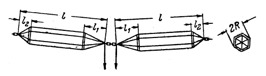
the antenna. The dipole contains several wires at each
shoulders shaped as a cylinder. Figure 1 shows the dipole Nadednenko.
For working at 40- 10 meters the sizes are: L= 8 meters, L1= 3
meters, L2= 1 meter, 2R= 1 meter. Diameter of wires is 1.5- 3
millimeters. |
Dipole struts can be both as metal as wooden.
As usual, metal struts has the shape
as a circle, wooden struts has the shape as a polygon. Wires are
attached to struts any possible way. Wires at ends of shoulders
carefully are welded. As usual, a 300- Ohm two wire line is used
for feeding of the antenna. Antenna radiates waves with horizon
polarization. By Radio 1959 |
|
|
Figure 1 |
||
|
|
||
|
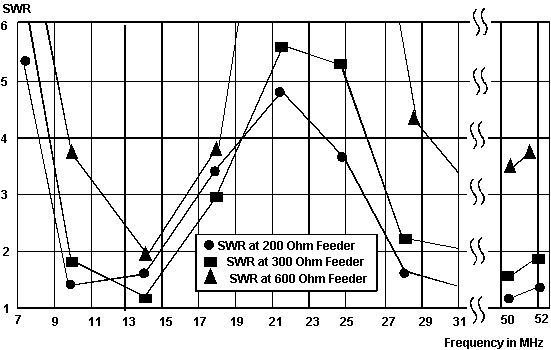
Calculations of input impedance and DD (for horizon radiation) of the dipole Nadenenko
located at 10 meters above real ground with above mention dimensions
(L= 8 meters, L1= 3 meters, L2= 1 meter,
2R= 1 meter, diameter of wires is 2 millimeters) are shown
below. You can see, it is possible to
use a 50- Ohm coaxial cable with a 1:4 transformer if restricted
bands (30, 20, 10 and 6 meters) are used. |
The data is
obtained with help of a free antenna program MMANA (MININEC based).
Left diagram is a section of the volumetric diagram directivity
of plane X-Y at a zenith corner of the maximum radiation. The
right diagram is section of the volumetric diagram directivity
of plane X- Z. Also at the right down corner of the pictures is
a table with antenna impedance. |
|
|
|
||
|
|
|
|
|
|
|
|
|
|
Page 64 |
|
 |
 |
 |
 |
Just for Fun:

Powered byIP2Location.com
Thanks for your time!
Last Updated:
February 23, 2020 16:04