


|
|
 |
 |
 |
|
|
Antentop is FREE e-magazine devoted to Antennas and Amateur Radio an
Special page devoted to
Window Dipole Antennas with Capacitive Loads

Custom Search
| ANTENTOP- 01- 2005, # 007
|
Window Dipole Antennas with Capacitive Loads
|
|
|
|
||
|
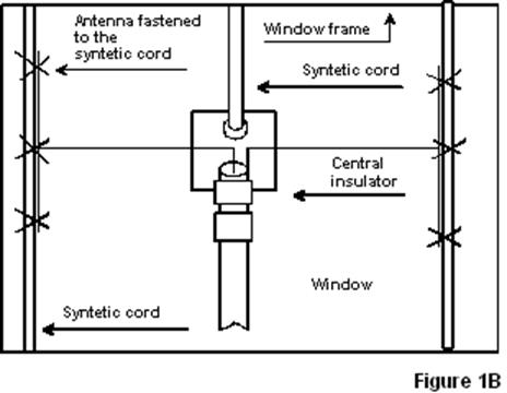
Figure 1 A window dipole antenna
with capacitive loads of central installation |
|
|
|
Adjustment
of the both antennas is simple. A SWR- meter or HF- bridge (see
References [1])
is connected to feed points of the tuned antenna. Gradually shorten
'moustaches' (symmetrically each moustache) of the antenna to
minimum SWR or when antenna input impedance is active (has no
reactive component) at needed frequency. At shortening moustaches
the moustache wires roll up to a little coil. Parameters of the Window Dipole Antenna with Capacitive
Loads of Central Installation Theoretical
parameters of the antennas (copper, wire in 1-mm (18- AWG) diameter)
were simulated with help of MMANA (see References [2]). |
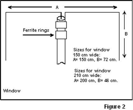
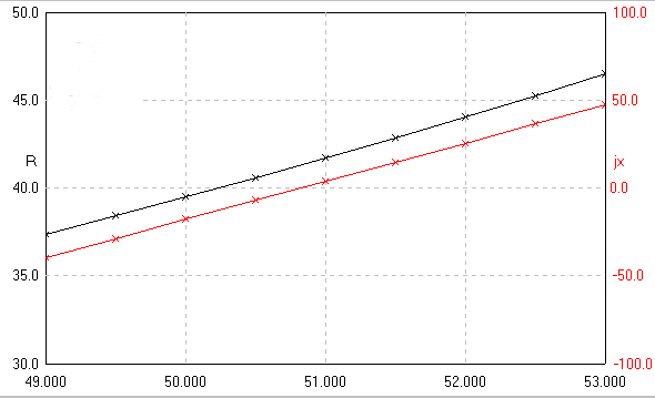
Figure 3 shows the
input impedance of the antenna installed at window 150-cm wide.
Figure 4
shows the input impedance of the antenna installed at window 210-cm
wide. Theoretical input impedance for 'narrow' antenna is
42- Ohms, for 'wide' antenna is 60- Ohms. The data are very good
matched with my practical measurement of the antennas. A 50- Ohm
coaxial cable should be used for feeding of the antennas. This
one can be connected directly to antenna feed points, as it is
shown at Figure 1. A 75- Ohm coaxial cable is possible
to use for the antenna installed at wide (210 cm) window. Figure 5
shows a SWR at 50- Ohm coaxial for 'narrow' antenna shown at Figure 1.
Figure
6 shows a SWR at 50- Ohm coaxial for 'wide' antenna
shown at Figure 1.
Theoretical gain for the antennas is near 1,5-
1,7 dBi. |
|
|
|
||
|
Figure 3 Input impedance of 'narrow' antenna |
||
|
|
||
|
|
Page 50 |
|
 |
 |
 |
 |
Just for Fun:

Powered byIP2Location.com
Thanks for your time!
Last Updated:
February 22, 2020 21:00