


|
|
 |
 |
 |
|
|
Antentop is FREE e-magazine devoted to Antennas and Amateur Radio an
Special page devoted to
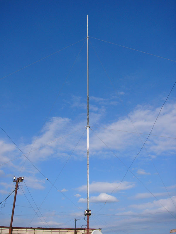
Ground Plane for the 40,-30,-20 and 17- meter
Bands

Custom Search
|
ANTENTOP- 01- 2012, # 016 |
Ground Plane for the 40,-30,-20 and 17- meter Bands |
|||||||||||||||
|
Table 1
shows data for the matching unit. All inductors are coiled by
wire in 2- mm diameter (12- AWG). Inductors are air- winding.
Diameter of each inductor is 40- mm. Gap between coils is 3- 5-mm.
The gap should be defined at the tuning of the antenna. High-
voltage ex- USSR capacitors K15U-1
are used in the matching unit. Vacuum
ex- USSR relay V1V did
switching on the matching circuit. All matching circuits were
sitting in aluminum box by dimension 330x200x130- mm. Figure
3 shows the design of the box. (There are matching
circuits for the 80/75- meter Band inside the matching box. However,
the antenna could not provide satisfaction operation on the bands.
So I did not use the antenna on the bands) |
 |
|||||||||||||||
|
Table 1
Data for parts for the matching unit
|
||||||||||||||||
|
|
Page-43 |
|||||||||||||||
 |
 |
 |
 |
Just for Fun:

Powered byIP2Location.com
Thanks for your time!
Last Updated:
February 17, 2018 22:07