


|
|
 |
 |
 |
|
|
Antentop is FREE e-magazine devoted to Antennas and Amateur Radio an
Special page devoted to
Autodyne Synchronous Regenerative
Receiver

Custom Search
|
ANTENTOP-
01- 2012, # 016 |
Autodyne
Synchronous Regenerative Receiver |
 |
|
|
|
|
|
|
Sergey Starchak |
|
The receiver was made on the base of the regenerative
receiver from the Reference
1. Receiver from Reference 1 was made for HF- Band 11.7- 12.1-
MHz and at the receiver was used autodyne synchronous reception.
Figure 1 shows schematic Autodyne
Synchronous Regenerative Receiver from Reference 1. After hours of the experimental work the schematic
was changed. Figure
2 shows improved variant of the autodyne regenerative
receiver. The receiver works at 5.9- 12.1- MHz. Some notes on
the Receiver. Coil L1 that is used as
antenna may be made from a coaxial cable in diameter 4- 8 mm |
Capacitance of the cable
between L1 and VT2 is 47- pF. It was
used a length of an usual audio cable
from a microphone wire. Three capacitors C3, C5
and C8 connected to bridge allow eliminate stray generation of
the VT2. VT1 is emitter follower.
Receiver may work without this one. Variable Resistor R3 is
used for changing spectral components in the sound. It used at
reception SSB/CW. Audio amplifier should have
small amplification because the regenerative receiver provides
big enough audio output. |
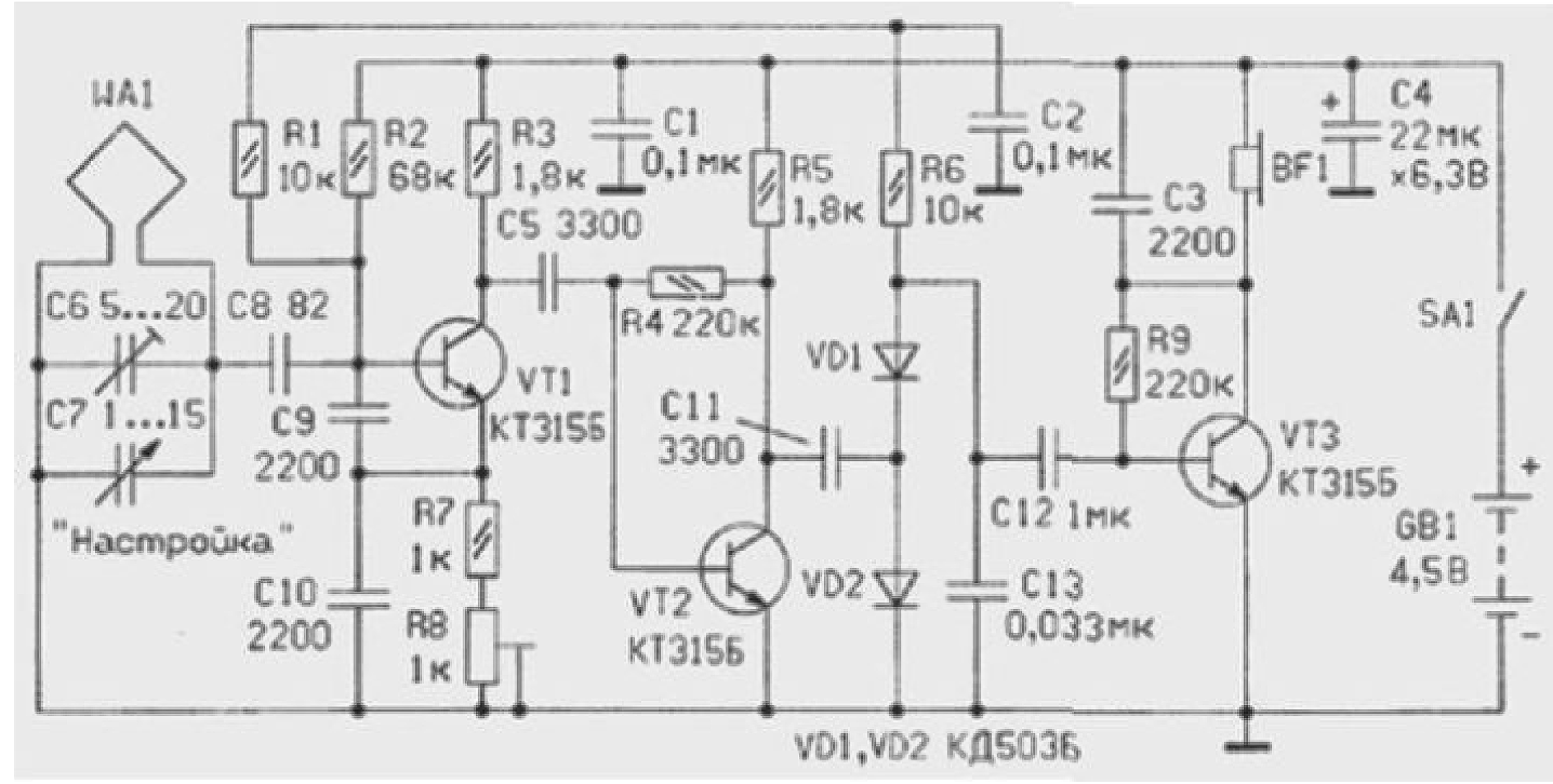 Figure 1 Autodyne Synchronous Regenerative Receiver |
|
|
|
|
|
|
Page- 85
|
85 86
 |
 |
 |
 |
Just for Fun:

Powered byIP2Location.com
Thanks for your time!
Last Updated:
January 19, 2020 13:53