

|
|
 |
 |
 |
|
|
Antentop is FREE e-magazine devoted to Antennas and Amateur Radio an
Special page devoted to
Antennas UA6AGW. Modification and Development

Custom Search
|
ANTENTOP- 01- 2013 # 017 |
Antennas UA6AGW. Modification and Development |
||||
|
|
|
||||
|
The capacitor C2 is switched on into the antenna with help
of a two- wire line. It is possible use to almost any design of
the two wire line. Antenna mast at my antenna installation has
length near 11- meter. The two wire line going from the bottom
of the loop is near 8- meter long. Coupling loop for the antennas Design and sizes of the coupling loop that used for the
antennas is the same as for antennas described in the Reference 1. Below there are several simple rules how to install the
coupling loop. At
first, find on the antenna loop a point
that is equidistance from left and right side of the C2. It is
the point of symmetry of the antenna. At
second, find the point of symmetry of
the coupling loop. The coupling loop is mounted in the top of
the antenna loop. Point of symmetry of the coupling loop should
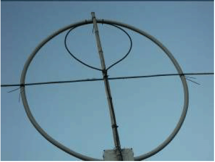
concur with the point of symmetry of the antenna. Figure 6
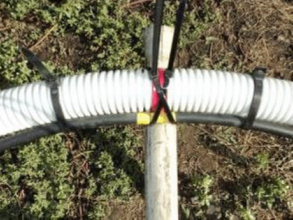
shows the coupling loop on the antenna. At
third, to fasten with help of the cable
ties the coupling loop to the antenna loop at the distance of
6- 8- cm from the point of symmetry of the antenna loop. Figure 7
shows the bonding. Antenna ������� UA6AGW V.20.00 The antenna was designed and made by Igor Kulikov,
UA3GDX (QTH: Gryazi, Lipetsk Region).
Figure 8
shows the design of the antenna. Loop of the antenna made from
a water tube in diameter of 2/3 inch. It was a tube with outer aluminum cover and inside plastic
form. Aluminum cover was used like the braid in the loop in the
design of the Antenna UA6AGW. A coaxial cable was inserted into
the tube. Braid of the coaxial cable was the inner conductor of
loop in the design of the Antenna UA6AGW. Central conductor of
the coaxial cable did not use to. Capacity of the capacitors C1
and C2 are shown approximately and depend on the antenna installation.
However, it looks like that capacity of the C1 should be close
to 8- 15- pF and capacity of C2 should be close to 24- 30- pF. |
Figure
6 Coupling Loop on the Antenna Loop
Figure
7 Bonding of the Coupling Loop to
the Antenna Loop Horizontal wires in the antenna design made of a copper wire in diameter
of 3- mm. The wires are going along plastic fishing poles. The
poles hold the form of the antenna. Such rigid design allows rotate
the antenna on to needed direction. Figure 9 shows the view of the antenna on a roof.
Figure
10 shows the close-up view of the antenna. |
||||
|
|
|||||
|
|
|
||||
|
|
Page- 39 |
||||
 |
 |
|
 |
Just for Fun:

Powered byIP2Location.com
Thanks for your time!
Last Updated:
January 9, 2020 22:26