


|
|
 |
 |
 |
|
|
Antentop is FREE e-magazine devoted to Antennas and Amateur Radio an
Special page devoted to
Soviet Legendary HF Receiver KUB- 4

Custom Search
|
ANTENTOP- 01- 2013 # 017 |
Soviet Legendary HF Receiver KUB- 4 |
|||
|
|
|
|||
|
|
||||
|
The
regenerative HF receiver was designed by a group of ham radio
in the Leningrad Central Radio Laboratory in the 1929. It was
in the group: B. Guk, S. Briman, A. Kershakov and B. Dobrozhansky.
The group was called in Russian "Korotkovolnovaya Udarnaya Brigada", or, in
English translation:
"HF high-extensive work team". So, the receiver was
named KUB- 4. Digit "4" means that just four tubes there
were used in the receiver. Actually, there were used five tubes
but the fifth one was used as a high-ohmic
variable resistor. The
prototype of the receiver was a regenerative HF Receiver designed
by B. Dobrozhansky in 1928- 1929 years. At the times Armstrong
still held patent on his superheterodyne
so lots countries produced regenerative receivers for all purposes-
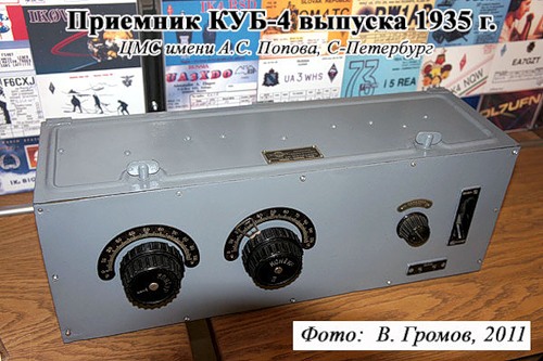
for military, navy and civil application. Figure 1 shows the receiver KUB- 4. Figure 2
shows schematic of the receiver KUB- 4. The
receiver KUB- 4 was produced since 1930 till 1942 in the Leningrad,
at the Kozitsky Radio Plant. Figure 3 shows a Label of the receiver
KUB- 4. The receiver had five bands that could cover the frequencies
1.5... 30.0- MHz (some receivers had the upper band a little lover
or a little higher the 30.0- MHz). The needed band was chosen
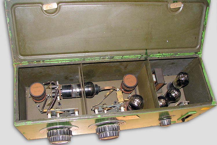
with the help of plug- in inductors. Unused inductors were placed
in a separate box or fixed to the upper cover inside of the receiver.
Such design had the own advantages and disadvantages... The receiver
KUB-4 had weight 8.0- kg and dimensions 500 x 143 x 180- mm. Power
battery with +120- V for plate, +40- V for the second grid, +
4-V for heater and 2- V for the first grid was required for the
receiver. |
Figure
1A Receiver KUB- 4 Front View
Figure
1A Receiver KUB- 4 Inside View |
|||
|
|
|
|||
|
|
|
|||
|
|
||||
|
|
|
|||
|
|
Page- 87 |
|||

 |
 |
|
 |
Just for Fun:

Powered byIP2Location.com
Thanks for your time!
Last Updated:
January 9, 2020 22:47