

Antentop is FREE e-magazine devoted to Antennas and Amateur Radio an
Special page devoted to
Symmetrical ATU

Custom Search
|
ANTENTOP- 01- 2015 # 019 |
Symmetrical ATU |
|
|
|
|
|
|
|
|
|
|
|
By: Vasily Perov, DL1BA (ex UK8BA) |
|
Prototype
of the tuner was made by VK5RG. The tuner
was found by me at "Das DARC Antennenbuch" (Reference
1). However at the book there was given only brief
description of the unit. The tuner takes my attention and by trial-and-error
method I found the design (data for Inductors and Capacitors)
of the tuner. Figure 1
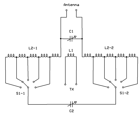
shows schematic of the Symmetrical ATU. Pay attention that at the tuner
the rotary switches S1-1 and S1- 2 do shortening of the unused
turns. The Symmetrical ATU is kind of usual two Pi- circuits,
C1 is capacitor at hot end- capacitor that tune the inductor L2
to resonance and C2 is capacitor at cold end- capacitor that does
matching for the load. Figure 2 shows design of the Symmetrical ATU. |
All three inductors are placed in row. The inductors
are wound by copper wire in 1.5- mm diameter (15- AWG). Inductor
L1 contains 4 turns and placed between matching inductors L2-1
and L2-2. Inductors wound on a dielectric plate (PCB plate without
foil) by dimensions 150x 80x 2mm. Two row holes were drilled in
the plate. The rows were 50- mm apart and it was 3- mm distance
between the holes. At first
step the inductors were being wound on to a form in 50- mm diameter.
Then the dummy inductor was taken off from the form and inserted
into the plate turn by turn. Inductor L1 contains 4 turns. Inductors L2- 1 and L2- 2 have 16 turns each. |
|
|
|
|
Figure 1 Schematic of the Symmetrical ATU |
|
|
|
|
|
Page- 63 |
|
63 64
 |
 |
|
 |
Just for Fun:

Powered byIP2Location.com
Thanks for your time!
Last Updated:
January 5, 2020 16:36


