
Antentop is FREE e-magazine devoted to Antennas and Amateur Radio an
Special page devoted to
Cliff Dweller's Antenna

Custom Search
|
ANTENTOP- 01- 2017 # 021 |
Cliff Dweller’s Antenna |
|
|
|
|
Cliff Dweller's
Antenna |
|
|
|
|
|
|
By K. E.
Hughes, W6CIS Credit Line: Radio and Television News,
January, 1956 |
|
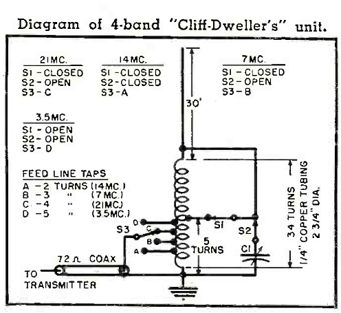
The accompanying diagram of the
author's "Four- Band Cliff Dweller's" is self
explanatory and might be of interest to other readers. Let me say at the outset that
such an antenna will not replace a good three- element beam on
20 or 60-foot high doublet on 80; however, considering the space,
cost and easy of adjustment, it gives a very good account of itself. Basically, the antenna functions
as an 1/8 wave on 80, ¼ wave on 40, ½ wave on 20
and ¾ wave on 15, being base loaded on all except 20 meters
where it is voltage- fed from the parallel resonant tank. The
vertical radiator is made up of five six-foot length of 0.5 inch
diameter surplus whip. In the author's case, the whip is guyed
with two sets of three guys each (light sash line, spring loaded
at the lower ends to allow for shrinkage) at 12 and 24 foot levels.
The antenna can be used at ground
level (if well clear of buildings, trees, etc.) or well off the
ground, using ground plane wires as an effective ground. In the author's installation,
the tuning unit is 8 ½ feet off the ground, at the same
height as the aluminum patio roof. This roof, plus a heave copper
ribbon running to a good ground rod, makes up the "ground
system." The cold end of the coil is truly
cold on all bands. The switches, S1, S2, and S3 are actually heavy
copper clips, although relays or knife switches could be used
if available. The capacitor can be any variable type with a maximum
capacity in the neighborhood of 100 pF.
A National TMS- 100 would be suitable. Adjustment of the tuning unit
was extremely simple. A grid dipper should be used in determining
the proper setting for the S1 tap, as well as getting the correct
number of turns in the complete coil for resonance at 3.5 MHz. |
The next step is to determinate
the correct feed point for the coax. If a SWR bridge is available,
it amounts to finding the point which gives the lowest SWR on
the feedline. If no bridge is available, the feed point can be
found by observing reflected reactance in the final amplifier
tank. With correct tap points at the antenna, the PA tuning will
be very nearly the same with or without the feedline coupled to
the transmitter. Results have been excellent, considering
the size of the system. The transmitter was free from TVI and
no change was noted when switching to this vertical radiator. As an example of its possibilities,
only Europe is needed for WAC on 3.5- MHz while running 450 watts
input. It is hoped that this idea may be of some help to those
amateurs living in so- called "impossible locations." 73! W6CIS |
|
|
|
|
|
|
|
Page- 47 |
|
47
 |
 |
|
 |
Just for Fun:

Powered byIP2Location.com
Thanks for your time!
Last Updated:
January 4, 2020 14:07


