

|
|
 |
 |
 |
|
|

Antentop is FREE e-magazine devoted to Antennas and Amateur Radio an
Special page devoted to
Ferrite Clips and RF Current Sniffer

Custom Search
|
ANTENTOP- 01- 2020 # 024 |
Ferrite
Clips and RF Current Sniffer |
|
|
|
|
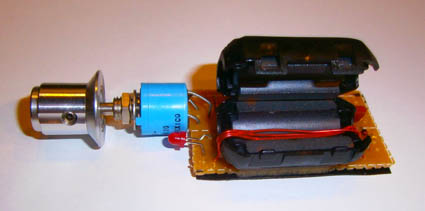
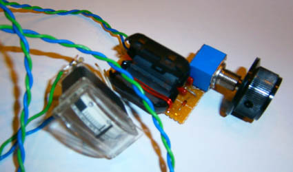
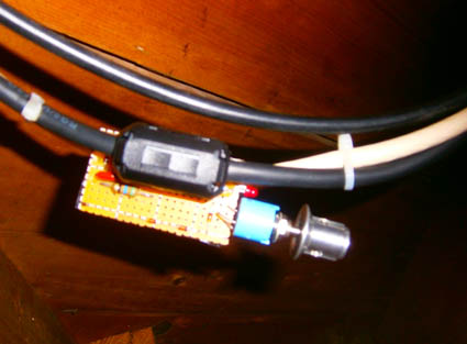
Take a look to RF Current Sniffer
with meter Indicator. (Of course, it is possible use or analog
arrow meter indicator either usual DMM.) On the ferrite clips
wound three turns of the copper wire in 0.7-mm diameter (diameter
of the wire does not matter, may be any suitable). Detector diode
is 1N4148. This diode works up to 100- MHz. Lower part of the ferrite clips is glued to the PCB
by epoxy. Upper part of the clips allows connect the clips to
coaxial cable. Arrow meter (or DMM) is connected to the device
through wires in length of 70- cm. Ever widespread current arrow
meter with full scale 1- mA allows make very sensitivity measurements compare to current meter with LED indicator. Instead of analog
meter it is possible use a DMM that is turn on to voltage range.
DMM may provide another kind of measurements and you do not need
adjust the POT that limit the current through the arrow current
meter. Figure
6 shows design of the RF Current Sniffer with arrow
meter Indicator. So, with these two RF current meters I decided make
measurements of RF current flowing on outer braid of the coaxial
cable going from my Beverage Antenna (http://www.antentop.org/023/va3znw_beverage_023.htm).
Of course, the measurement gives only quality result, not strictly
science, but anyway I may judge how useful the ferrite clips are.
The first measurements I made without RF choke (without
ferrite clips on the coaxial cable). RF Current Sniffer with LED
Indicator was installed on the coaxial cable coming from my Beverage
Antenna and wiring in my shack. The LED may glow up at all bands-
from the 160- to 6- meter. For glow the LED transmitter should
run 80 W at 160 and 80 meter and 50- to 30 W at 40- 6- meter.
Figure 7 shows glowing LED on the
RF Current Sniffer with LED Indicator. Then, ferrite clips were installed
on the coaxial cable (see Figure 2). The RF current flowing on the outer
braid of the coaxial cable is greatly reduced. At 160 and 80 meters,
the LED has already stopped glowing, at 40 and 30 meters the LED
is barely glowed at power of 100 watts. The "glowing"
power on the other high-frequency bands also has significantly
decreased. After this experiment I ordered another batch in 40
ferrite clips (ebay, from China) and
I hope to significantly reduce the remaining RF current on the
outer braid of the coaxial cable. I
used the RF Current Sniffer with Arrow Meter Indicator to measure the RF
current on the power cord of my radio station. After the installation
of ferrite clips the RF current has dropped significantly. After
the installation of ferrite clips, at my opinion, noise on the
receiver mode as well goes down. So, the ferrite clips improve
my radio at two positions- at transmitting and receiving mode. 73! de VA3ZNW |
Figure
5 Design of the RF Current Sniffer with LED Indicator
Figure
6 Design of the RF Current Sniffer with Arrow Meter
Indicator
Figure
7 Glowing LED on the RF Current Sniffer with LED Indicator |
|
|
|
|
|
Page- 98 |
 |
 |
|
 |
|
|
|||
Just for Fun:

Powered byIP2Location.com
Thanks for your time!
Last Updated:
January 30, 2021 21:39