
Antentop is FREE e-magazine devoted to Antennas and Amateur Radio an
Special page devoted to
Dipole Antenna for the 50-MHz Band

Custom Search
|
ANTENTOP-
01- 2021, # 025
|
Dipole
Antenna
for the 50-MHz
Band |
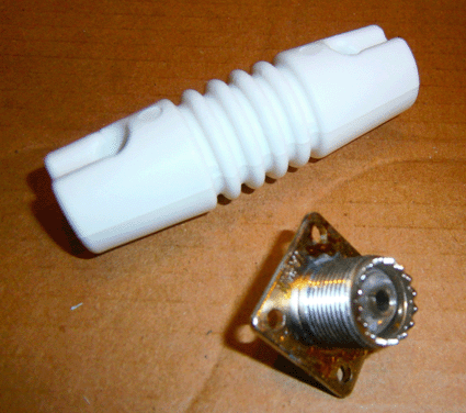
 Figure 2 Dog Bone Insulator with SO- 239 Connector |
|
|
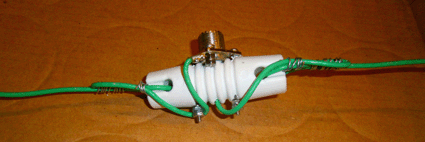
Figure 3 Connector Mounted on Dog Bone Insulator and Antenna
Wire Connected to SO- 239 Connector |
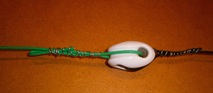
Figure 4 Egg Insulator at the End of the Antenna |
|
Let's discuss the practical implementation of the
antenna. Before tuning, each side of the dipole had 160 centimeters
of wire. The antenna was installed at height of 2 meters above
the ground for the tuning. By symmetrically shortening the sides
of the antenna, this antenna was tuned to minimum SWR at the frequency
of 50.1- MHz. The SWR and input impedance
was measured by MFJ- 259B. The device was connected directly to
the antenna. At the resonant frequency of 50.1- MHz the antenna
had input impedance of 75- Ohm that is the theoretical one. Figure 5 shows the final dimensions
of the antenna tuned to 50.1- MHz. |
Connection of the feeding coaxial cable to the SO-
239 connector was protected with Coax-Seal tape. A 100 feet long
RG- 8 coaxial cable was used to run from the antenna to transceiver.
Figure 6
shows the center insulator with connected feeding coaxial cable.
The antenna was installed in a sloping position,
the lower end of the antenna was at the height of 2 meters from
the ground the upper end of the antenna was at the height of 4
meters from the ground. Figure 7
shows the antenna at its location. |
|
Page- 53 |
|
 |
 |
|
 |
|
|
|||
Just for Fun:

Powered byIP2Location.com
Thanks for your time!
Last Updated:
December 30, 2021 21:37


