

|
|
 |
 |
 |
|
|
Antentop is FREE e-magazine devoted to Antennas and Amateur Radio an
Special page devoted to
Field Strength Meter for the 137 kHz Band

Custom Search
|
ANTENTOP-
02- 2003, # 003 |
Field Strength Meter
for the 137 kHz Band |
||
|
|
|||
|
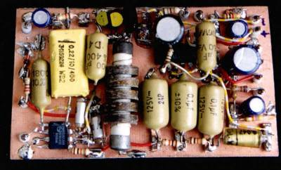
The remaining part of the circuitry is on a second board.
Here we find the mixer, an IC type SA612BN, incorporating the
oscillator circuit. The ubiquitous NE612 can be used as well. |
|
||
|
|
|||
|
|
|||
|
|
|||
|
|
|
||
|
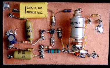
The values of C10, C11 and C16 were dictated by the choice
of coil L2. I used a 2 mH hf choke from my junkbox, as shown in
one of the photographs. C10 and C11 are the usual capacitors found
in a Colpitts oscillator. C12 isolates L2 from the DC on pin 6
of the mixer. I found the BB104 type dual varicaps in my junk
box. Two in parallel were necessary to obtain the required tuning
range. The lower frequency was set by selecting C16. The upper
limit was found to be a bit high and this was corrected by adding
R7. RV1 is the tuning control. (The unmarked resistor between
the wiper of RV1 and the varicaps is 120 kohm.) Selectivity
of a direct conversion receiver is determined by a low pass filter
in the audio path. A high degree of selectivity is required here
because of the extremely strong station DCF39 at 138.82 kHz, only
1020 Hz above the upper limit of the band. I use a RC-filter with
three sections, each having a time constant RC=1 mS. At first
resistors and capacitors of the same value were used in the three
sections and this is the situation seen in one of the photographs. |
Later I realised that a better response
is obtained when the loading of a section on its preceding one
is decreased and this resulted in the values seen in the circuit
diagram. The lower limit of the frequency response is set by the
time constant RC=(R17 + RV2)*C21 respectively
RC=R16*C20. The response of the metering circuit shows a maximum
at about 36 Hz and is 3 dB down at 16 and 88 Hz. The output of the low pass filter is
fed to the two sections of a dual opamp type UA747. The upper
opamp feeds the headphones. Volume is controlled by RV3 in the
feedback path. The lower opamp feeds a
digital multimeter that must be capable of measuring AC in the
millivolt range up to about 2 V. Preset resistor RV2 is adjusted
when calibrating the instrument. I choose to make the audio output,
as indicated by the DVM, 1000 mV when the instrument is placed
in a field of 5 mV/m. The reading is
linear up to about 10 mV/m maximum (2
V on the meter). |
||
|
|
|
||
|
|
Page 56 |
||
 |
 |
 |
 |
Just for Fun:

Powered byIP2Location.com
Thanks for your time!
Last Updated:
March 6, 2020 22:10