

|
|
 |
 |
 |
|
|
Antentop is FREE e-magazine devoted to Antennas and Amateur Radio an
Special page devoted to
Field Strength Meter for the 137 kHz Band

Custom Search
|
ANTENTOP-
02- 2003, # 003 |
Field Strength Meter for the 137 kHz Band |
||
|
|
|||
|
The instrument is fed by a 9 V battery. The LED is a small
one that gives a clear indication of the instrument being switched
on when drawing a current of only 2 mA. To make the gain of the RF amplifier and mixer independent
of battery voltage the supply for these stages is stabilized at
6.2 V by a zener diode. R12 was selected so that the zener keeps
control for battery voltages down to 7 V. There is no need to
stabilize the supply for the opamps because their gain is controlled
by negative feedback and therefore hardly depending on the supply
voltage. The instrument draws about 17 mA from a new battery.
CalibrationTo calibrate
the field strength meter the instrument must be placed in a magnetic
field of known strength. |
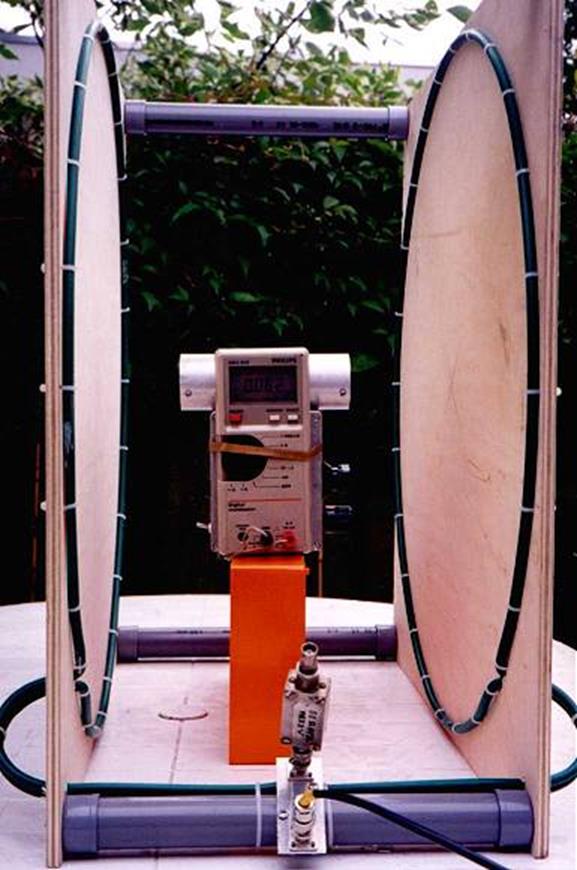
This can be produced by a pair of so called "Helmholtz
coils". German scientist Helmholtz already in the 19th century found by computation
that a homogeneous magnetic field can be produced by placing two
circular one-turn coils of radius r metres parallel to each other
at a distance of r metres and with their axes coaxial. When a
current I is made to flow through each of the coils in the same
direction a homogeneous field of H=1/(1.40*r)
(3) is generated in a considerable volume between the coils. H
in A/m; I in amps; r in m. I constructed
a pair of Helmholtz coils with r=0.292 m as shown in one of the
photographs. The coils are connected in parallel and in series
with a 50 ohm resistor. |
||
|
|
|
||
 |
|||
|
|
|||
|
|
|
||
|
|
Page 57 |
||
 |
 |
 |
 |
Just for Fun:

Powered byIP2Location.com
Thanks for your time!
Last Updated:
March 6, 2020 22:11