

|
|
 |
 |
 |
|
|
Antentop is FREE e-magazine devoted to Antennas and Amateur Radio an
Special page devoted to
Multirange Trap Antennas

Custom Search
|
ANTENTOP-
02- 2004, # 006
|
Multirange
Trap Antennas |
|
|
|
||
|
|
||
|
|
||
|
Multirange
trap antenna: history and fundamentals Recently
multirange trap antennas are widespread among radioamateurs. As
matter of fact, the type of antennas was invented in the USA by
H. K. Morgan, US patent # 2229856, 1938 (by reference [1]).
Probably the first article about a trap antenna was published
in reference [2] at 1940.
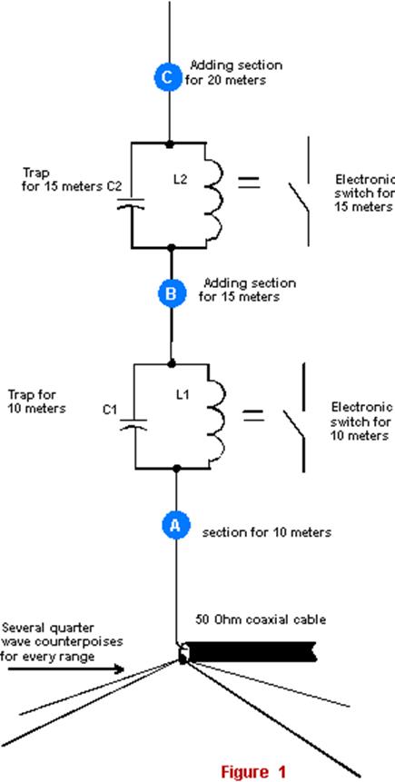
So, what is the antenna and how is it work? Let's see it on the
example of a ham vertical trap antenna in order to simplify a
problem. Figure 1 shows us
a schematic of such antenna. |
Igor
Grigorov, Rk3ZK 15
meters: By length of the Section B we tune the antenna
parts "Section 1 plus L1C1 plus Section B" to resonance
to 15-meters. Trap L2C2 turn off upper antenna parts behind the
trap from operation of the antenna when 15 meters range is used. 20
meters: By length of the Section C we tune the antenna
parts "Section 1 plus L1C1 plus Section B plus Section C"
to resonance to 20-meters. |
|
|
Figure
1 A ham vertical trap antenna 10
meters: Section A is tuned for operation on 10-meters
by its length. Trap L1C1 turn off upper antenna parts behind the
trap from operation of the antenna when 10 meters range is used. |
And
so on for other ranges: In the similar way the antenna
would be tuned for others ham HF- ranges. You see, it is possible
to do an antenna for any number of HF- ranges! But there are several
lacks. Upper parts of the antenna behind a proper trap do not
use (or, practically do not use) for radiation. Another lack is
that the antenna wire is broken at several places by trap circuits.
Every trap circuits should be tune in to own resonance frequency.
Trap circuits must have high temperature stability, because the
antenna is used at the open air. Traps work at a resonance mode
so a high level of RF voltage is across trap capacitors at transmission
mode. Thereof it needs to use a high quality capacitor for every
of the traps. Vertical
trap antenna WA1LNQ: One of the most popular sample
vertical trap antenna is the antenna WA1LNQ [2].
The antenna is used on 10 and 15 meters. Figure
2 shows the scheme for the antenna. The
antenna made from two insulated from each other metal tubes by
length of 240,7 (section A) and 62,9 (section B) centimeters and
in OD 18 to 25 millimeters. The length of an insulating insertion
is 5,8 centimeters. Over the insulating part is spooled the trap
spool. A copper tube in diameter of 3 to 5 mm is used for the
spool, and the spool contains 2 turns with step 1 turn on 25-mm
of winding. Average diameter of the trap spool is 55-mm. As a
trap capacitor is used a length of a 50-Ohm coaxial cable with
an initial length equal to 80 centimeters. Tuning
of the Antenna WA1LNQ: At first, tune the antenna in
10-m range. At the tuning the length of the coaxial cable, that
makes the trap capacitor, is gradually shortened to minimum SWR
in 10 meters. After this, tune the antenna to minimum SWR at 15
meters. It is possible to do by a small changing of the length
of the upper section B. Below
you can see input impedance, SWR and DD of the antenna W1LNQ.
The figures are obtained with the help of Free Antenna Simulation
Program |
|
|
|
||
|
|
Page
47 |
|
47 48 49 50 51 52 53 54 55 56 57 58 59 60 61
 |
 |
 |
 |
Just for Fun:

Powered byIP2Location.com
Thanks for your time!
Last Updated:
February 23, 2020 20:43