


|
|
 |
 |
 |
|
|
Antentop is FREE e-magazine devoted to Antennas and Amateur Radio an
Special page devoted to
Some Thoughts on Regenerative Receivers

Custom Search
|
ANTENTOP- 01- 2010, # 012 |
Some Thoughts on Regenerative Receivers |
|
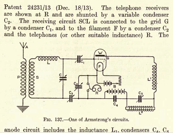
One of Armstrong Regenerative Receiver Credit Line: Thermionic Tubes in Radio Telegraphy
and Telephony, by: John Scott- Taggart, The Wireless Press LTD,
1921 |
|
|
Effectively increases the "Q" of the tuned
circuit by the concept of "negative
resistance." Any circuit that accomplishes this will do the
trick. Typically, an oscillator circuit, such as a Hartley, Colpitts,
or the like is chosen. One then sets the loop gain of the oscillator
circuit by some means to be just below the point of oscillation.
Later, it will be seen that there are some clear design advantages
to some circuits over the others. Runs in "oscillation" mode, if desired, to
act as a direct conversion or autodyne detector for CW or Single
Sideband signals. The oscillation mode provides the BFO, or course. The workings are not dependent on vacuum tubes versus
transistors. The real problems in any design at least, are: 1. Interaction with the antenna, and QRM generated
by the receiver itself. "Grounded Grid" or equivalent
isolation amplifier does the trick here. An un-tuned grounded
gate FET amplifier seems to be the modern choice. |
2. There is massive interaction with tuning as a function
of regeneration setting. If there is a way to separate detection
from regeneration, this problem can be addressed. One typical
vacuum tube design uses a Colpitts oscillator in parallel with
a plate or grid leak detector (my favorite for vacuum tube designs).
Another alternative (my Senior EE project in 1960!) was to insert
a cathode follower between the tuned circuit and the detector/feedback
vacuum tube).
Edwin H. Colpitts, "Oscillation Generator," Figure Credit Line: Wiki |
|
|
Page 65 |
63 64 65 66 67 68 69 70 101 102
 |
 |
 |
 |
Just for Fun:

Powered byIP2Location.com
Thanks for your time!
Last Updated:
January 22, 2020 21:42

