


|
|
 |
 |
 |
|
|
Antentop is FREE e-magazine devoted to Antennas and Amateur Radio an
Special page devoted to
Some Thoughts on Regenerative Receivers

Custom Search
|
ANTENTOP- 01- 2010, # 012 |
Some
Thoughts on Regenerative Receivers |
|
|
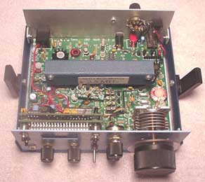
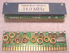
Plug-in coils -- the classic solution, but clumsy to
do, and you have to have some place to conveniently store the
un-used coils. My own early sets used these, mostly because I
could buy a nice set of short wave and broadcast band coils, versus
winding my own coils. If you note pictures of early commercial
sets for marine use, there was a coil box near the receiver. The
"Sierra" QRP transceiver suffers from this problem. |
A design that uses only a single coil in the tuned circuit such as the Colpitts design is
one such solution that greatly reduces the complexity of band
switching. Of course, a Hartley oscillator design uses a single
tap on the coil, but again, this is an additional source of complexity
due to the tap on the coil. The Colpitts design does require a
DC return for the cathode in the case of vacuum tubes or source
in the case of FET designs. |
|
|
|
|
|
|
Plug- In Coils at Radio "Sierra" Credit Line: http://www.w0ch.net/sierra/sierra.htm |
||
|
By the way, FETs have an advantage as they are high
input impedance devices like vacuum tubes, and do not load the
tuned circuit to any degree. Both of the two commercial regenerative
receivers I have use FETs in the detector and isolation amplifier.
The MFJ-8100 has a series of inductors in series with a simple
single pole selector switch. The Ten-Tec 1253 uses nine separate
inductors, but switches them with a clever PIN diode and counter
circuit. Both of these designs use an isolation "front end,"
which eases the complexity of coupling into the tuned detector
circuit. It is generally agreed that designing a receiver for
a single or small range of frequencies is much easier than developing
a general coverage receiver. If you can get a 10:1 range of capacitance
change with a variable capacitor, for example, then you can expect
about a 3:1 tuning range (square root of the ratio of the maximum
to minimum capacitance). This problem rears its ugly head especially
in the case of varactor tuning, where the capacitance change range
is more modest. More about this later, with a couple of "real
life" receiver designs. The usual approach to fine tuning, when using a variable
capacitor is to have a "band set" capacitor and then
a "band spread" capacitor of about 10% of the value
of the main capacitor. |
To save money, an alternate approach is to use some
sort of mechanical vernier reduction drive, such as the MFJ-8100.
With varactor tuning, a secondary variable voltage source with
a smaller voltage variation range serves the same purpose. Kitchin
used a combination of varactor (fine) and variable capacitor (coarse)
tuning in one of his designs. If we are willing to accept a modest degree of increase
in complexity, the so-called "Regenodyne" receiver is
a good choice as a solution to the difficulties of developing
a wide coverage receiver. A Google search will turn up some extensive
discussions of this concept. The idea here is to have a regenerative receiver of
modest tuning range as a "back end" to a superhetrodyne
front end, which converts a series of band segments with a crystal
oscillator with a series of switched crystal frequencies. A somewhat
similar line of attack was used with the "Q Multiplier"
tuned/regenerative IF system on early vacuum tube general coverage
receivers. This was available from Heathkit. I had one on a Hallicrafters
S-20R, which was quite effective. The front end can be
pretty broad, and only need remove the image response. |
|
|
|
|
|
|
|
Page 68 |
|
63 64 65 66 67 68 69 70 101 102
 |
 |
 |
 |
Just for Fun:

Powered byIP2Location.com
Thanks for your time!
Last Updated:
January 22, 2020 21:52

