

|
|
 |
 |
 |
|
|
Antentop is FREE e-magazine devoted to Antennas and Amateur Radio an
Special page devoted to
EH Antenna for the 20- meter Band

Custom Search
|
ANTENTOP- 01- 2012, # 016 |
EH Antenna for
the 20- meter Band |
||
|
|
|
||
|
Fist copper sheet turns
around of the Polypropylene Tube and temporary hold by a length
of wire. Distance from the upper end of the tube to the foil should
be 15- 20-mm. Take hot soldering iron and solder the sheet in
3- places. You need to do it fast because the plastic tube may
be melted. Take wire for the phase inductor. Put wire to the seam
and do soldering the foil on the full length. |
Phase inductor has 2- 3
(3 better) turns of the insulated wire. Turn around the tube coils
of the inductor. Lower end of the inductor is inserted into the
hole in dia 2-mm onto the tube. Do not forget to tin the end.
Figure 2 shows soldering of the inductor to the upper copper
cylinder. Figure 3 shows the ready phase inductor. |
||
 Figure 2 Soldering of the Inductor to the Upper Copper Cylinder |
 Figure 3 Ready Phase Inductor |
||
|
Take the second copper sheet.
Do with it the same things as with the first one (to turn around
of the plastic tube hold by pieces of wire and do soldering in
several places). Pay attention that the second (lower) cylinder should
be placed on the distance apart of the first cylinder equal to
diameter of the tube. At our case it is 32- mm (see Figure 1). Next step is to measure the capacity between the cylinders. I used to a surplus Russian device E9- 5. Figure 4 shows the measurement. At the design of the EH- Antenna the capacity between the cylinders should be near 7- pF. Knowing of the value is needed for us to calculate (according to W5QJR reference book) a tuning inductor. Below I give you a calculated by me data for the inductor.Next step is to make the
tuning inductor. The inductor is coiled by enamel strand wire
in diameter 2- mm (12- AWG). Numbers of turns are 26 (calculated
value) but I recommend to coil 28- 29 turns. |
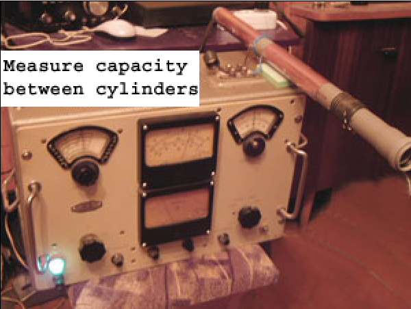 Figure 4 Measure the Capacity between
the Cylinders It should be done for purpose
of the tuning of the EH- Antenna because it is easy to remove
the coils then to add those ones. |
||
|
|
Page-48
|
||
 |
 |
 |
 |
Just for Fun:

Powered byIP2Location.com
Thanks for your time!
Last Updated:
January 19, 2020 12:54