
Antentop is FREE e-magazine devoted to Antennas and Amateur Radio an
Special page devoted to
EH Antenna for the 20- meter Band

Custom Search
|
ANTENTOP- 01- 2012, # 016 |
EH Antenna for
the 20- meter Band |
|
|
|
|
|
|
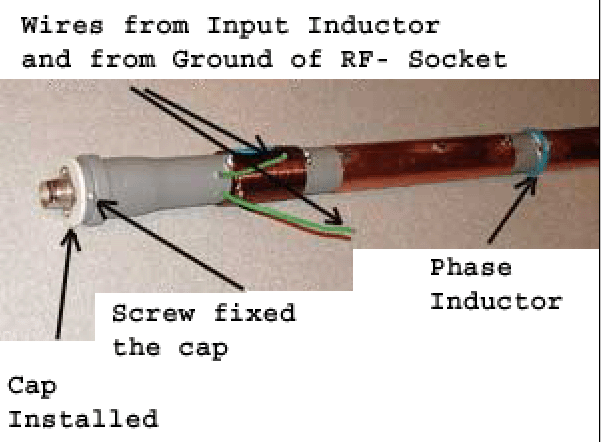
Do two holes in diameter
2- mm near the lower end of the tuning inductor. Pass through
the holes wires from the input inductor and ground of the RF-
Socket (Figure 11). Length of the wires
should be allowed to remove the cap from the tube without desoldering
the wires from the tuning inductor and RF- socket. It may be needed
for adjusting of the input inductor. Then fasten the cap to the
tube by screw. |
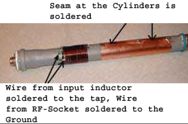
Figure 12 shows EH- Antenna with
the cap. Wire going from the input inductor is initially soldered
to the 4th- tap of the tuning inductor. Wire going from the ground
of the RF- Socket is soldered to the lower end of the tuning inductor.
Figure 13 shows the soldering
to the tuning inductor. |
|
 Figure 12 EH- Antenna with Cap. |
 Figure 13 Soldering Wires to the
Tuning Inductor |
|
|
All set! EH- Antenna is made! Tuning of the Antenna At the tuning process antenna
should be hanged up in the way that any subject should be placed
no more the 0.5- 1.0- meter apart from the antenna. Initially it would be good
to measure a resonance frequency of the antenna. Best way is to
use an RF- Spectrograph with a screen. I used to a surplus Russian
X1-50 spectrograph. Several words are here about of using of the spectrograph.
Almost any spectrograph has two pairs of terminals for analysis
of the "Black- Box" First terminal is "Output"
from where an RF is going. Second terminal is "Input" to where the
signal that came through the Black Box is going. So we need a
Black Box with Antenna inside in it. For the Black Box I used
to an RF- Bridge made by schematic of RZ4HK (Reference: Radio
#1, 1980, p.22). Figure 14 shows the Bridge. Turn on the bridge to the spectrograph and turn on
the antenna to the bridge. |
Now it is possible to find
with help of the spectrograph the amplitude frequency characteristic
of the EH- Antenna. Figure 15 shows RF Bridge connected
to the spectrograph. Figure 16 shows screen with the amplitude frequency characteristic
of the EH- Antenna. EH- Antenna should be turn on straight away
to the Bridge. RF Output and Input of the spectrograph may be
turn on to the bridge by the Spectrograph's cables. If the resonance frequency
of the antenna is lower the 14.15- MHz turn by turn remove turns
from the upper end of the tuning inductor. Stop on the frequency near 13.5-13.8 MHz. Then the tuning antenna
into resonance it is possible to do by changing gap between the
turns of the tuning inductor. After that turn on the EH- Antenna through SWR meter to the transceiver.
SWR meter should be connected straight away to the EH- Antenna.
Input inductor at the time should be closed. Change tap on the
tuning inductor by minimum SWR. Figure 17 shows SWR Vs Tap at my
EH- Antenna. Open input inductor. Change quantity of the turns
or geometrical sizes of the inductor by minimum SWR. Check the
resonance frequency of the antenna during the tuning. |
|
|
Page-51 |
||
 |
 |
 |
 |
Just for Fun:

Powered byIP2Location.com
Thanks for your time!
Last Updated:
January 19, 2020 13:00


