


|
|
 |
 |
 |
|
|
Antentop is FREE e-magazine devoted to Antennas and Amateur Radio an
Special page devoted to
Pencil Tubes

Custom Search
|
ANTENTOP- 01- 2012, # 016 |
Pencil Tubes |
|||||
|
|
|
|||||
 |
||||||
|
|
|
|||||
|
|
V.Sukhanov, A. Kireev Credit Line: Radio # 10, 1960, pp.: 49- 52 |
|||||
|
Below there are described some main schematics on the miniature "pencil"
tubes. The schematics came to us from the far 50- 60-s of the
20- Century. The schematics with pencil tubes were used at the
radio equipment that was installed practically anywhere - from
tank and submarine up to space ship. Radio Frequency Amplifier Figure 1 shows a typical schematic for a radio frequency amplifier. As usual
a tube was used with plate voltage 60- V, second grid voltage
35- 45-V, and 0- V at the first grid. The RF- Amplifier works
fine up to VHF- frequencies. (I.G.: I have seen such RF amplifiers that worked up to 180-
MHz.) Practically any pencil tubes
may work like a radio frequency amplifier. |
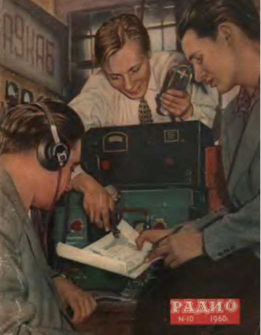 Radio # 10, 1960 Cover |
|||||
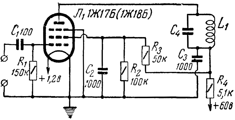 Figure 1 Radio Frequency Amplifier |
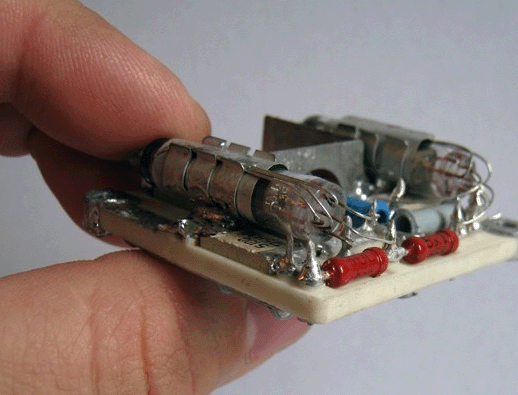 Module on the Pencil Tubes |
|||||
|
|
|
|||||
|
Header of the Article |
||||||
|
|
|
|||||
|
|
Page- 89
|
|||||

 |
 |
 |
 |
Just for Fun:

Powered byIP2Location.com
Thanks for your time!
Last Updated:
January 19, 2020 13:58