


|
|
 |
 |
 |
|
|
Antentop is FREE e-magazine devoted to Antennas and Amateur Radio an
Special page devoted to
Pencil Tubes

Custom Search
|
ANTENTOP- 01- 2012, # 016 |
Pencil Tubes |
|
||||
|
|
|
|
||||
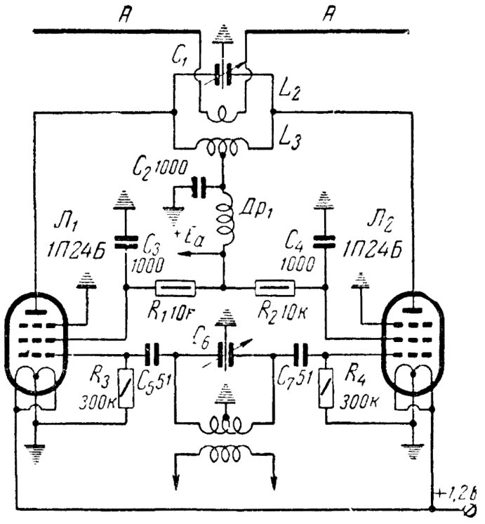 Figure 7 Schematic of RF Power Amplifier
for Frequencies Higher the 100- MHz |
|
|||||
|
Superregenerative Detector Receivers made on pencil tubes that was contained a Superregenerative Detector were widely used in military
and special application. Figure 8 shows a typical schematic of the Superregenerative Detector. Regenerative circuit made on
tube 1, quench generator made on tube 2. Quench voltage at the
second grid of the tube 1 should be in limits 20- 25- V. |
Level of the voltage more the 25- V just follows to increasing of the
pass band. Level of the voltage less the 20- V just decreases
sensitivity and stability of the Superregenerative
Detector. Sometimes (when saving battery power plays role) regenerative
cascade and quench generator combine in one tube. But stability
and sensitivity are suffered at this. |
|
||||
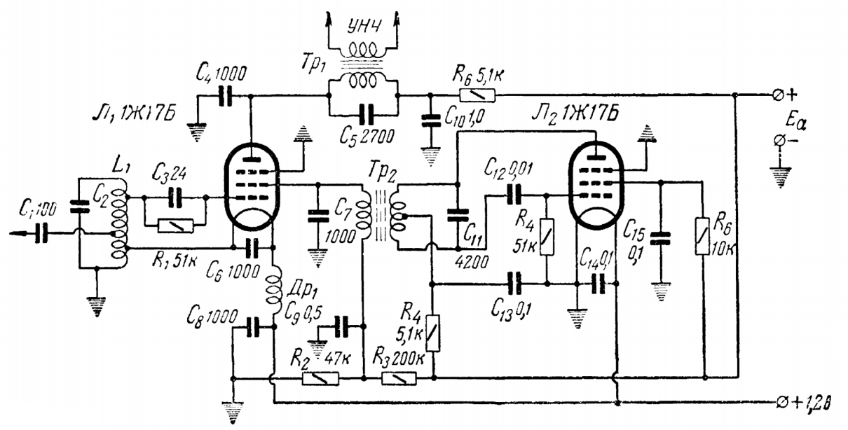 Figure 8 Typical Schematic of the
Superregenerative Detector |
|
|||||
|
|
Page- 92
|
|
||||
 |
 |
 |
 |
Just for Fun:

Powered byIP2Location.com
Thanks for your time!
Last Updated:
February 17, 2018 23:03