antentopSince2 July

** PLEASE DESCRIBE THIS IMAGE **


Antentop is FREE e-magazine devoted to Antennas and Amateur Radio an

Special page devoted to

VHF ATU

Custom Search


ANTENTOP- 01- 2017 # 021

Several Universal ATUs for the Whole Amateur HF Band


Several Universal ATUs for the Whole Amateur HF Band


By Igor Grigorov, VA3ZNW


It is not difficult to build an Antenna Tuning Unit (ATU) for any amateur HF band. Such device could be done with usual coils and capacitors. However the real problem is making a simple and effective ATU without lots switching and tuning that could work over a broad range of frequencies. Below there are given several different ATU that work effectively over all amateur HF bands from 160-10 meters, easy to do and easy to tune and easy to match antenna with transmitter. The ATU was tested with transmitters with 50 and 75 Ohm output.

 Universal ATU

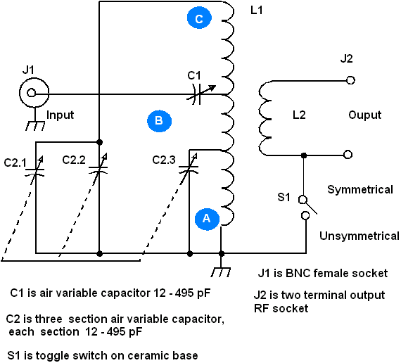
 Figure 1 shows schematic of simple and universal ATU that can capable of working on all amateur HF bands. Design of the unit is based on ATU made by Peter Linsley (G3PDL), Reference 1. I repeat the schematic with some changes and found to be very effective this one. This ATU is capable of matching the transmitter final stage of 50-75 ohms output to an antenna load of 20 to 300 ohms in the frequency range of 1.8-32 MHz with an SWR of no higher than 2:1.


How it works:

 In the 1.8 to 4-MHz range, the circuit consisting of L1, C2.1, and C2.2 is tuned to resonance with the input signal. Capacitor C1 is used for fine-tuning of the matching circuit with transmitter final.

 7 to 32 MHz: For operation in the range of 7 to 30-MHz range, the circuit consisting of the lower section A of coil L1 and variable capacitor C2.3 is tuned to resonance and the middle section B serves as a coupling coil for section A. C1 also provides the fine matching with the final amplifier stage. In the higher frequencies the upper part of the coil L1 acts as an RF choke and does not interfere with part A and B sections of the coil.

 For both ranges, the coupling coil L2 is a compromise for coupling to the antenna. By adjusting C1 and C2, satisfactory matching to the antenna can be achieved in both frequency bands. This ATU does not cover the new amateur band at 5 MHz. To use the ATU in the new band, a tap at 3.5 turns in section C of coil L1 needs to be added as shown in Figure 2.


Figure 1

Universal ATU


www.antentop.org

Page- 65


65 66 67 68 69 70 71


Just for Fun:

Map IP Address
Powered byIP2Location.com

Thanks for your time!

Last Updated:

January 4, 2020 14:30

** PLEASE DESCRIBE THIS IMAGE **

** PLEASE DESCRIBE THIS IMAGE **

2003entop