
Antentop is FREE e-magazine devoted to Antennas and Amateur Radio an
Special page devoted to
VHF ATU

Custom Search
|
ANTENTOP- 01- 2017 # 021 |
Several Universal ATUs for the Whole Amateur HF Band |
|
|
|
|
Figure 12 Simple ATU |
|
| The first winding of my transformer is contained 3
turns and the second has 30 turns. The first winding is wound with
wire from L1 coil. The second winding is wound with wire of 0.3
mm (#27-#25 AWG). However the second wire is depend on the design
of the coupling transformer, RF power going in to the antenna and
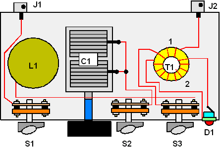
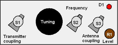
for characteristics of the LED. Design of the ATU is shown in Figure 13. The front view is shown in Figure 14.
Figure 13 Design of Simple ATU |
The capacitor C1 is behind the switch and its calibration
is located on the front panel. 1. Igor Grigorov. Universal ATU for the HF Bands, Radiolubitel KV and UKV, October 1999, p. 29
3. Igor Grigorov. Antennas: Tuning and Adjustment, Radiosoft, Moscow 2002,270 pages.
Figure 14 Front View of Simple ATU |
|
|
|
|
Page- 71 |
|
 |
 |
|
 |
Just for Fun:

Powered byIP2Location.com
Thanks for your time!
Last Updated:
January 4, 2020 14:34


