


|
|
 |
 |
 |
|
|

Antentop is FREE e-magazine devoted to Antennas and Amateur Radio an
Special page devoted to
Two Simple Low Pass Filters for 145 - MHz Band

Custom Search
|
ANTENTOP- 01- 2018 # 022 |
Two Simple Low Pass
Filters for 145- MHz Band |
|
|
|
|
However,
ever recently in our crazy tech epoch it is not everyone has a
Spectrum Analyzer in own home or access to such device at some
place. Without a Spectrum Analyzer it is possible to tune the
Low Pass Filter for 145- MHz Band to minimum SWR but
hard to adjust the internal rejection filters. In this case it
is possible to do a compromise variant of such filter-without
internal rejection filters. Schematic of a simple Low Pass Filter for
145- MHz Band without internal rejection filters is shown in Figure 8. |
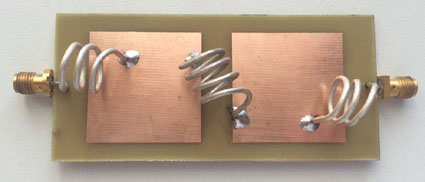
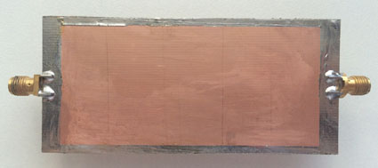
The
filter made on a piece of two sided PCB. Capacitors of the filter
are created on the board. Figure 9 shows
design of the filter. Figure 10 shows
view of the filter. Figure 11 shows
layout of the capacitors. The capacitors made on a PCB that has
thickness in 1.5- mm. However different PCBs depend on the stuff
and the thickness may have another capacity per square centimeter.
It is very useful to find the capacity per square centimeter and
re-calculate (if it should be done) the sizes of the capacitors
before the capacitors would be made. |
|
Figure 8 Schematic
of a simple Low Pass Filter
for 145- MHz Band (without internal rejection filters) |
|
|
|
|
|
Figure 9 Design
of the simple Low Pass Filter
for 145- MHz Band (without internal rejection filters) |
|
|
Figure 10 View
of the simple Low Pass Filter
for 145- MHz Band (without internal rejection filters) |
|
|
|
|
|
|
Page- 77 |
 |
 |
|
 |
|
|
|||
Just for Fun:

Powered byIP2Location.com
Thanks for your time!
Last Updated:
January 3, 2020 22:17