
Antentop is FREE e-magazine devoted to Antennas and Amateur Radio an
Special page devoted to
Antenna Switching Units

Custom Search
|
ANTENTOP- 01- 2018 # 022 |
Antenna
Switching Units |
|
|
|
|
|
|
To prevent connection of a receiver antenna
to a transmitter output or to simultaneously switch two transmitters
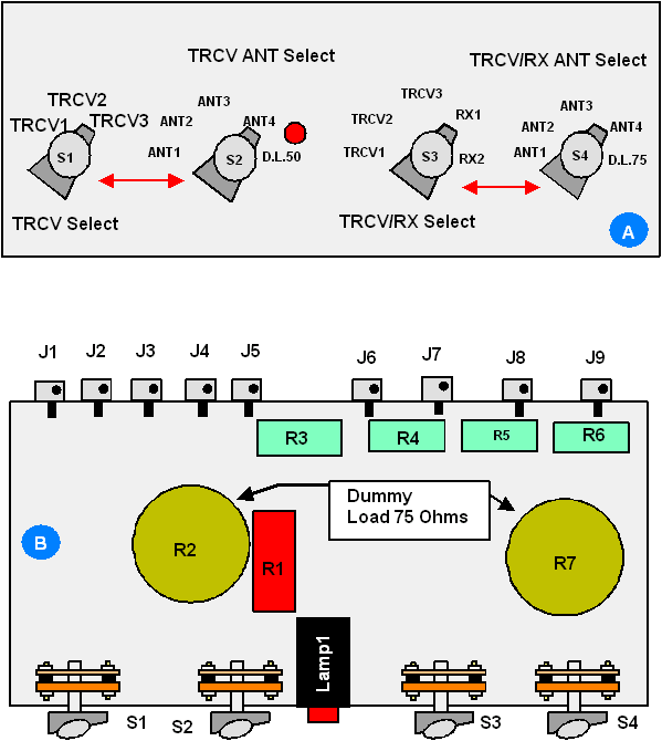
to one antenna, switches S2 and S4 should be independent of each
other (however it need pay attention when switching). How it works: Switch S1 selects operational
transceiver. Switch S2 selects an antenna for use with this transceiver.
Other auxiliary transceivers or receivers may be connected to
other antennas with help of switches S3 and S4. All antennas connected
to ASU are permanently grounded with help of R3, R4, R5 and R6
(100 K/2W) for electro-static bleed-off. Resistors R2 and R7 were
old commercial made 75 Ohm/25W dummy load.
To one of the dummy load was connected to bridge resistor 180
Ohm/5W that created new 50 Ohm dummy load. Figure 2 shows the views of the front panel (Figure 2A)
and inside design (Figure 2B) of the universal ASU. There were used usual ceramic galette rotary switches that work well for power levels
up to 200W. For higher power levels it is necessary to use special
powerful ceramic galette rotary switches
intended for operation in high-current, high voltage circuits.
Montage and component mounting should meet RF guidelines. ASU for RF-Bridge/ATU If in the shack there are several separately
units such as an ATU, transceiver, and RF-bridge it is possible
to hook up the equipment with help of special ASU. In this case
it is possible tune the system ATU plus Antenna with the RF-bridge.
Even though a transceiver or the ATU may have an SWR-meter built-in
it, it would be useful to use an RF-bridge for antenna tuning.
RF-bridge gives the real impedance of the system Antenna plus
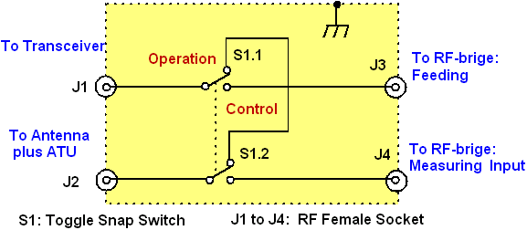
ATU. Figure 3 shows schematic
for such unit. |
Figure
2 Front Panel (A) and Inside Design (B) of
the Universal ASU When S1 switched to the Control position,
RF power from transceiver goes to the RF-bridge and ATU with antenna
as well connected to the Bridge. In tuning mode it should be used
level of RF power that intended for operation of the RF- bridge.
My RF-bridge required near 0.5 W of RF power. When the system
is tuned, S1 should be switched to Operation position and RF power
may be increased. Figure 4 shows the system Transceiver- ASU- ATU-
RF-bridge. |
|
|
Figure
3 ASU for RF-bridge |
||
|
|
|
|
|
Page- 81 |
||
 |
 |
|
 |
|
|
|||
Just for Fun:

Powered byIP2Location.com
Thanks for your time!
Last Updated:
June 24, 2018 17:43


