
Antentop is FREE e-magazine devoted to Antennas and Amateur Radio an
Special page devoted to
Antenna Switching Units

Custom Search
|
ANTENTOP- 01- 2018 # 022 |
Antenna
Switching Units |
|
|
|
|
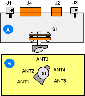
Figure
10 Design of unit
A1 |
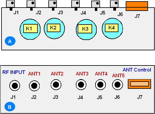
Figure
11 Design of unit
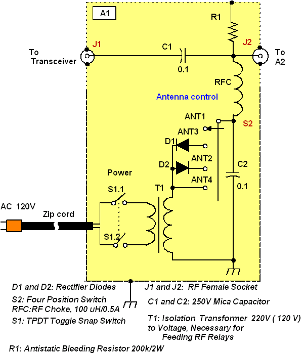
A2 Schematic diagram for the unit A1 is shown
in Figure 12. Schematic
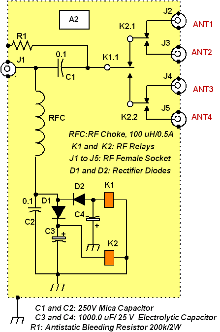
diagram for the unit A2 is shown in Figure
13. |
|
The switching unit A1 with code circuit
is installed in the shack. The switching unit A2 (with decode
circuit and RF relays) is installed on the antenna installation
site - on a roof.
Figure
12 Schematic Diagram
of Unit A1 |
Figure
13 Schematic Diagram
of Unit A2 |
|
|
|
|
Page- 85 |
 |
 |
|
 |
|
|
|||
Just for Fun:

Powered byIP2Location.com
Thanks for your time!
Last Updated:
June 24, 2018 18:09


