|
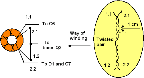
Figure 3 shows design of the RF transformer T1. Transformer T1 is wound on a
ferrite ring with a permeability of 600 and OD of 10 mm. The winding
consists of 10 turns of 0.3-mm wire (28 AWG). The wires are twisted
together, at a rate of one twist per centimeter, and are wrapped
equally around the entire core, with identical spacing between
turns.
The RF Generator was assembled
in cabinet with sizes 160x90x100-mm. The cabinet was made from
two sided PCB. Generator was made by Manhattan style. Design should
be compact and rigid as possible. The generator was fed from internal
NiCad battery on 12V/800mA.
Reference
1.
Radio, 1999, # 5, p. 59
73! de VA3ZNW

Figure 3
Design of the RF Transformer
|

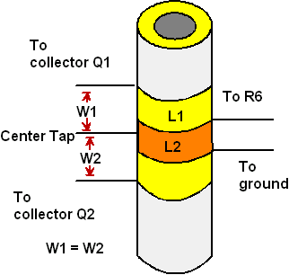
Figure 2
Design the Inductors of the RF Generator
|
|
Table 1 Data for Inductors of the RF Generator
|
Band,
MHz
|
L1
|
L2
|
R6,
Ohm
|
|
1.4
to 3.2
|
15+15 turns on diameter 42 mm, wire diameter 0.5mm
(24 AWG);
length
of winding 10 mm
|
2 turn over CT L1; wire diameter 0.5mm (24 AWG)
|
75
|
|
3.2
to 8.0
|
12+12 turns on diameter 17 mm, wire diameter 0.5mm
(24 AWG);
turn
to turn
|
3 turn over CT L1, wire diameter 0.5mm (24 AWG)
|
100
|
|
8.0
to 30.0
|
4+4 turns on diameter 8 mm,
wire diameter 0.5mm (24 AWG):
turn
to turn
|
2 turn over CT L1; wire diameter 0.5mm (24 AWG)
|
120
|
|


