


|
|
 |
 |
 |
|
|
Antentop is FREE e-magazine devoted to Antennas and Amateur Radio an
Special page devoted to
A Multi Band Tube 10 w QSK Transceiver

Custom Search
|
ANTENTOP- 01- 2010, # 012 |
A Multi Band Tube 10 w QSK Transceiver |
|
|
|
|
Parts At the transceiver I used Russian
tubes. Table 1 shows their international alternatives (thanks to G3FCK) Table 2 shows data
for inductors. Values of capacitors C31 and C32 are real for specific
impedance of your antenna. If you would like use several antennas
with different impedances you need use plug- in inductor (L8C26C31C32)
for each antenna (or use variable C31 and C32). |
Design Transceiver was made on a chassis
with dimensions 200 x 240 x 40- mm made from two- sided copper
plate PCB. Pattern of the parts at the chassis the same as the
pattern at the Figure 1.
Plug- in inductors was made on the base from old octal tubes.
Figure 4
shows the design. It is possible to add some modifications to
the transceiver- milliampermeter for metering plate current at
the V6 and install variable capacitors instead fixed C31 and C32.
Dimensions of the transceiver would be increased but operation
in the Air improved. Beware: Turn off high
voltage when change the plug- in inductors! |
|
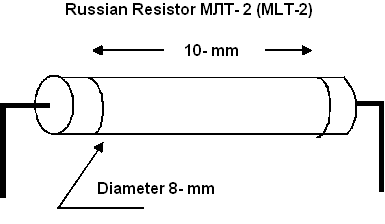
Figure
2 Russian Resistor MLT- 2 |
|
|
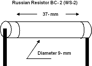
Figure
3 Russian Resistor WS- 2 |
|
|
Figure 4 Design of the Plug- In Inductors |
|
|
|
Page 78 |
 |
 |
 |
 |
Just for Fun:

Powered byIP2Location.com
Thanks for your time!
Last Updated:
January 22, 2020 22:54

