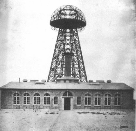
|
Therefore,
the Shortening Factor of the helical antenna was 8.33. To
calculate the Shortening Factor, we divide 2000/4, that
is, we find the length of the quarter-wave vertical, which
is equal to 500 meters, and then divide the length by 57,
that is, by the real height of the helical antenna.
Nikola Tesla
never mentioned the helical antenna as a "helical antenna",
and he considered this antenna to be part of his "magnifying
transmitter", designed to transmit electrical energy
over the Earth's surface, and not to transmit electromagnetic
energy to the Air. We will not enter into a discussion with
Nikola Tesla about the work of his helical antenna, and
move on other designs of historical helical antennas.
Shortened Helical Antennas of Broadcasting
Radio Stations
Shortened
helical antennas were used in the beginning of the era of
the radio broadcasting in the early of the 20th in the MW
and LW broadcasting radio stations. In some old radio technical
reference books (from 40- 50 years of the 20- century),
which were in the library of the Kharkov Institute of Radio
Electronics, where I studied, I found quite detailed drawings
of helical antennas of Long-Wave and Medium-Wave for broadcasting
radio stations from the 20-30s. Unfortunately, at that far
time I did not write down the bibliographic data of these
books, but only did sketches of the helical antenna designs.
Figure 2 shows the
design of the typical helical antenna of the broadcasting
LW or MW radio stations of the 30s of the 20th century.
It was almost a classical helical antenna. Three wooden
masts formed a triangular frame on which the antenna wire
was wound. The height of the mast was approximately 30 meters.
At the top of the helix it was installed a capacitive load.
The load had several (3- 10) umbrella wires placed at small
angle- 30- 60 degree to the helix.
Such helical
antennas may be tuned for work in the broadcasting band
from 2000-1000 meter. So Shortening Factor of the antenna
may be 16.6 (for the wavelength of 2000 meter) to 8.33 (for
the wavelength of 1000 meter). However such antennas were
rare in use and then wires antennas replaced the helical.
Wires antennas (most of them designed by Marconi Company)
were simple in design and predictable for simulation.
|

Picture 5 1904
Image of Wardenclyffe Tower

Picture 6 Tesla's Magnifying
"Apparatus for Transmitting Electrical Energy"
(US Patent 1,119,732)
Covered the Basic Function of the Device Used at Wardenclyffe
|


