
Antentop is FREE e-magazine devoted to Antennas and Amateur Radio an
Special page devoted to
HF Helical Antennas: Theory and Practice

Custom Search
|
ANTENTOP-
01- 2020, # 024 |
HF Helical Antennas: Theory and Practice |
|
|
|
|
|
|
Do not use house equipment-
metal heating and water pipes for grounding system of the antenna.
It will cause RFI to different houses electronic equipment and
bring noise to the receiver connected with the helical antenna. For the ground system of
the window helical antenna use 2- 3 counterpoises with length
equal to lambda/4 for the each operating band of the antenna.
The counterpoises must have strong plastic insulation. The ends
of the counterpoises must be insulated. Counterpoises may be installed
initially on the wall of the house and then go to into opposite
sides. Counterpoises must be hidden from access of human and pet.
Device Artificial Ground
is very welcome at the grounding system. Thick wire (it may be
length of a coaxial cable) in 2- 5 meter length (find optimal
length by experiment) should be connected to the device. Artificial
Ground allows do optimal tuning the grounding system. When the helical antenna
is
tuned
to
the
resonance
frequency
it
should
be
measured
the
antenna input impedance. RF-bridge, MFJ-259 or any other device
may do the
job.Lots of the
shortened asymmetrical helical antennas that were tested by me
in the window opening had input impedance near 30- 60 Ohm, so,
usual 50- Ohm coaxial cable may be connected to the antennas without
any matching device between antenna and the coaxial cable. The
high input impedance (compare to the theoretical one) of the shortened
helical antenna installed at the window opening could be explained
by losses of the RF energy by nearest objects and the losses in
the grounding system of the antenna. |
If the input impedance is different at least to 20 percent from the wave
impedance of the feeding coaxial cable it should be installed
simple L- matching device between the antenna terminals and the
coaxial cable. Good choice if the electrical length of the coaxial
cable is multiplied by lambda/2. Then it should be measured antenna
resonance frequency at the end of the coaxial cable. Most common
method is by measuring the SWR at the coaxial. In some cases the
helical antenna (or simple L- matching device between the antenna
terminals and coaxial cable) may be need some additional tuning.
Free program MMANA (References 10)
has option for calculation of the L- matching circuit. Practical
Installation of the Dipole Helical Antenna in the Window Dipole helical antenna may be installed in concrete
house at (in) the window. Let's take a look for installation of
the dipole helical antenna at the window with dimension 140 x
210- cm. Figure 23
shows vertical installation of the dipole helical antenna at the
window with dimension 140 x 210- cm. Figure 24 shows horizontal installation of the
dipole helical antenna at the window with dimension 140 x 210-
cm. Figure 25
shows diagonal installation of the helical dipole antenna at the
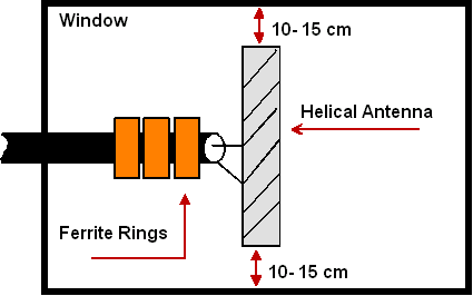
window with dimension 140 x 210- cm. Distance between the tops of the dipole helical antenna
and sides of the window frame should be at least 10- 15- cm. In
this case influence of the window frame and concrete building
to the top of the helical antenna would be insignificant. |
|
|
Figure 23 Vertical Installation
of the Dipole Helical Antenna at the Window with Dimension 140
x 210- cm |
||
|
|
|
|
|
Page- 29 |
||
05 06 07 08 09 10 11 12 13 14 15 16 17 18 19 20 21
22 23 24 25 26 27 28 29 30 31 32 33 34 35 36 37
 |
 |
|
 |
|
|
|||
Just for Fun:

Powered byIP2Location.com
Thanks for your time!
Last Updated:
January 30, 2021 14:48


