
Antentop is FREE e-magazine devoted to Antennas and Amateur Radio an
Special page devoted to
Antenna with Rotating Directional Pattern for the 80, 40, 20, 14 and 10 meter Band

Custom Search
|
|
|
|
ANTENTOP- 01- 2020 # 024 |
Antenna with Rotating Directional Pattern
for the 80, 40, 20, 14 and 10 meter Band |
|
|
|
|
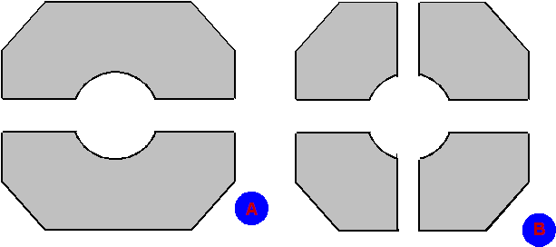
Figure 5 Stator
of the Capacitor
Figure 6 Rotor
of the Capacitor |
|
|
|
|
|
Several words about
the ATU:
Transformer T1 isolated ATU (with antenna system) from the transmitter.
The transformer was made on a ferrite ring, it is possible use
any suitable ring. Soviet radio-amateurs ever used to a ferrite
from yoke transformer of TV. Inductor L1 may be tapped (should
be chosen right tap for every band) or used a variometer
inductor. The impedance of the antenna system is not 50-Ohm. At
that time most of Soviet hams used to transmitters with tube PA
that can be matched with load having impedance from 10 to 1000
Ohm. So, if you do not use a tube PA, you should use additional
ATU between the antenna and transistor transceiver. |
How the antenna works: First at all it needs with help of the C6 capacitor
set up direction to the receiving station. The direction is set
up on to maxima receiving signal. Then with help of the C5 set
up the optimal direction diagram of the antenna. Inductor L1 should
be installed to optimal inductivity (find in practical way) for
the antenna. After that PA should be tuned to maxima output power.
That is all, happy QSO! 73! de RA6AA and UV6AF |
|
|
|
|
|
Page- 60 |
 |
 |
|
 |
|
|
|||
Just for Fun:

Powered byIP2Location.com
Thanks for your time!
Last Updated:
January 30, 2021 19:47


