

Antentop is FREE e-magazine devoted to Antennas and Amateur Radio an
Special page devoted to
J - Antenna for 160,15 and 10(FM) meters

Custom Search
|
ANTENTOP-
02- 2003, # 003 |
J - Antenna for 160,15 and 10(FM) meters |
|
|
|
||
|
|
||
|
|
||
|
by Valentin Gvozdev , RU3AEP, http://www.vgvozdev.narod.ru/ |
||
|
|
||
IntroductionAfter getting my first amateur license I had to think, what antenna to
build for a top-band (160 m), I realized,
that conditions are too bad for it. I live in a 7-floor house,
which has a roof with a high slope (about 35-40 degrees), which
is very dangerous to operate on it. Also, the house is almost
completely surrounded by wide streets and electrical wires going
along them. After long thinking, I concluded, that there is only
one possibility to make an antenna - to hang up a long wire from
my roof to the roof of another house. Unfortunately, any dipole-type
antenna was unacceptable, because in this case my apartment would
have been too far away from the feed point of the antenna, and
the condition of right angle (90o) between feeder and
antenna itself could not be satisfied. Fortunately, in that time
I have read about one very old, but not frequently used antenna
- so called Zeppelin-antenna with a matched feeding. |
Classical
design with an opened line Actually, this is shortly described in well-known book ("Antennenbuch"), written by DM2ABK (Karl Rothammel), but has been recently developed by Sergey Makarkin (RX3AKT), a radioamateur
from Moscow, who has published a good article in "Radio-Design"
journal (N2, 1998). Classical
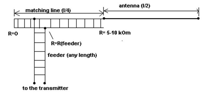
design is presented below (Figure
1). As it can be seen, there is feeder with rather
high impedance (~300-600 Ohm), and 1/4-wavelength matching line.
From one end, this line is shortened, and here its impedance is
just a zero (current is high, but voltage is almost zero). Another
end of this line is connected to the long wire, which has length
exactly 1/2 wavelength. At this point, the impedance is very high
(several kiloohms). That is why,
a big voltage exists here during a transmission. This is quite
suitable for a wire feeding, because a 1/2-wavelength has high
impedance when fed from the end. |
|
|
Figure 1. Classical Zeppelin-antenna design |
||
|
The
feeder from the transmitter with a specific impedance Rf
is connected to the matching line in the point, where impedance
of the latter is equal to that of the feeder. Such point is usually
located not so far from the shortened end. If everything is done
properly, feeder may have any length and SWR is closed to 1:1
in rather narrow band, central frequency of which is determined
by the geometrical size of matching line and antenna. |
Classical design with a coaxial cable for 160 meters This design can be used
almost without change, but instead of symmetrical feeder a coaxial
cable can be used to connect the whole system to the unsymmetrical
output of the transmitter (Figure 2). Using of a coaxial
cable instead of an open line has one big advantage in contrast
with the symmetrical transmission line it is almost insensitive
to the environment, weather conditions and can be placed really
everywhere.
|
|
|
|
|
|
|
|
||
 |
 |
 |
 |
Just for Fun:

Powered byIP2Location.com
Thanks for your time!
Last Updated:
March 1, 2020 22:37


