


|
|
 |
 |
 |
|
|
Antentop is FREE e-magazine devoted to Antennas and Amateur Radio an
Special page devoted to
J - Antenna for 160,15 and 10(FM) meters

Custom Search
|
ANTENTOP-
02- 2003, # 003 |
J - Antenna for 160,15 and 10(FM) meters |
|
|
|
||
|
the transceiver through SWR meter - to the feeder. The resistor here serves as a loading instead of the antenna wire. After assembling of the system, put RF power (1-2 W or
even less is enough) on some frequency inside 160 m band into
line and watch the SWR. If the line is completely out of resonance,
SWR will be closed to infinity, and no power will be dissipated
on the resistor. Then, the frequency should be found, which gives
the sharp minimum of the SWR. It has to be around 1800 KHz. Here,
the SWR is usually less than 1.5:1, and the full power of the
transceiver is dissipated on the resistor, which means, that the
matching line works well. When touching the 'hot' end |
of the loading, it may be seemed, that is really very
hot- this is due to the high HF voltage, which causes skin burning
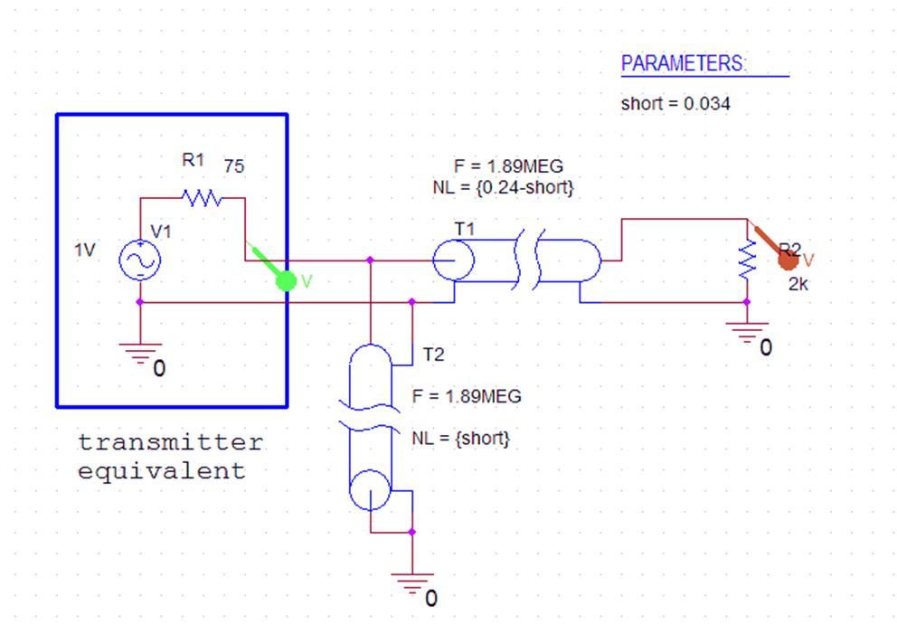
(be careful to do it, even by low power of RF source!). For better understanding of these processes is useful to look to the
results of simulation of this system using Pspice
simulation software. The equivalent schematics (Figure
3) includes voltage source V1 in series with 75 Ohm
resistor (which emulates output resistance of the transmitter),
two coaxial lines T1 and T2 and loading R2. Since Pspice
does not allow to set lengths of the transmission lines directly
in length units, they are set in wavelengths (NL) on the specified
frequency (in our case, F=1.89 MHz). |
|
|
Figure 3. Equivalent schematics for matching
line, used for simulation. |
||
|
Calculated
frequency response is presented on the Figure
4. Here, the colors of the traces correspond with the
colors of the voltage markers on the schematic. As it can be seen,
on the resonant frequency about 1.95 MHz there is sharp voltage
maximum on R2 (red trace), which reaches 2.6V- it is about 5 times
more, than the voltage on the transmitter's output (green trace).
Also it should be noted, that on the resonant frequency voltage
on R1 (green trace) is closed to one half of source voltage ( in our case, 1V). Practically, it means,
that there is good matching between transmitter and the antenna
and most of generated power is dissipated on the loading. |
After the resonance has been found, it should be shifted up to the desired frequency. To do this, the end of the cable should be cut carefully in several steps, watching the resonance frequency each time, which must increase with each cut. After you achieve the desired frequency, the matching line is almost ready, and you can mount the whole antenna system in the chosen place. It should be noted, that the minimum of the SWR in mounted antenna is usually 20-30 kHz down, compared to the value achieved by the tuning on the resistor. |
|
|
|
|
|
|
|
|
|
 |
 |
 |
 |
Just for Fun:

Powered byIP2Location.com
Thanks for your time!
Last Updated:
March 1, 2020 22:40