


|
|
 |
 |
 |
|
|
Antentop is FREE e-magazine devoted to Antennas and Amateur Radio an
Special page devoted to
J - Antenna for 160,15 and 10(FM) meters

Custom Search
|
ANTENTOP-
02- 2003, # 003 |
J - Antenna for 160,15 and 10(FM) meters |
|
|
|
||
|
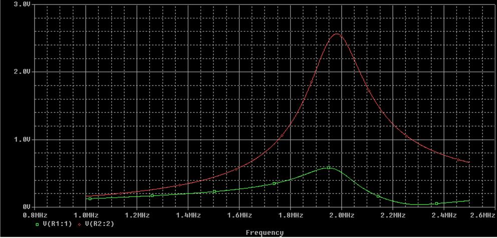
Figure 4. Frequency response of the matching
line in range 1- 2.5 MHz |
||
|
|
||
|
In
my case, the antenna for 160 m band had a minimum of SWR at 1875
kHz (about 1.3:1), on the edges of the band SWR increased to 2.0...
2.5:1, since the design is a narrow-band one. Compared to my previous
dipole, which hanged on the low height (about 5 meters over the
ground) along the building, this antenna exhibited much better
transmission efficiency and higher signal to noise ratio while
receiving. The
same design for 10 meters - cheap and simple.
About 2 years after getting my first amateur license I upgraded it to the higher license class, which allowed me to operate on 10 meters SSB. In that year, there was a perfect propagation on 10 meters band during the daylight time, and I needed an efficient antenna to work on it. Probably, in some time I will have something like rotable multielement Yagi on my roof, but now it seems to me inaccessible as the Moon due to many factors. After some time I decided to repeat what I built for 160 meters for 10 meters, proportionally reducing all geometrical sizes of the antenna wire and matching line. Since the wavelength on 28500 KHz is just 10.52 m, a half-wavelength dipole should be about 5 meters, and the total length of the coaxial matching line will be 10.52/(4*1.52) = 1.73 m. The feeder is connected to the line 23 cm away from the shortened end. These sizes are relative small and the whole antenna system may be placed without being mounted on the roof, for example just from your window to the neighboring tree. I made the antenna from a 2 mm copper wire with a plastic insulators at the ends, using 75 Ohm coaxial cable for feeder and matching line. There was nothing |
difficult to tune the
system - I hanged the antenna across my apartment and adjusted
the length of the matching line as described above for 160m design
using 1.80 m as the starting value. The only thing that should
be noted is that the actual resonance of the line is very sensitive
to the length variations, so on the final steps the cable should
be cut in 1 cm (!) portions or even less to not miss the desired
resonance position. After I hanged the antenna on the designated
position, SWR was less then 1.5 on all frequencies ranging from
28200 to 29000 KHz. This antenna is really very simple and cheap, but nevertheless, I allowed me to establish many connections with Europe and even Far East using just about 10 Watts of power. I really enjoyed working on 10 meters ether in local communications and transnational QSOs, and this was made possible just by several hours of time, dedicated to the antenna building and tuning. About working
on other bands- some facts and theory.
Though LW antennas
with a feeding through coaxial transformer, which were described
above, seem to be monoband, this appeared
not completely true. As I found out, the whole system has many
resonant frequencies, and some of them, are inside or near amateur
bands and can be used for working on these bands. As it could
be expected, operation on the frequencies, which are twice more
that 'native' ones, is impossible. When using an antenna for 160
m, on 80 m band observed SWR is closed to infinity and the transmission
efficiency is not more that by using a |
|
|
|
|
|
|
|
|
|
 |
 |
 |
 |
Just for Fun:

Powered byIP2Location.com
Thanks for your time!
Last Updated:
March 6, 2020 21:59