

|
|
 |
 |
 |
|
|
Antentop is FREE e-magazine devoted to Antennas and Amateur Radio an
Special page devoted to
Half-Loop Antennas

Custom Search
|
ANTENTOP-
03- 2003, # 004 |
Half-Loop Antennas
|
|
|
|
||
|
A 125W radioset combined with a tuned loop antenna is sufficient to fulfill
the mission requirement using the Near Vertical Incident Signal
(NVIS propagation). This will be further improved due to frequency
management and the new generations of HF modems which will bring
a lower threshold of sensibility. II DEVELOPMENT
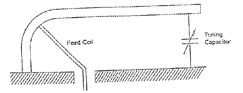
OF A NEW MOBILE TUNED FRAME ANTENNA II.1 Principle The mobile tuned loop antenna is a "half-loop" set-up vertically
on a metal surface which achieves a full
loop equivalence. The metal surface like a mobile platform (truck
or shelter, ship's cabin,...) must have
a good electrical continuity. Thie half-loop is half the size
of a full loop and makes installation possible on small vehicles
on the move. The half-loop is folded and joined at each end to the platform's earth.
One end is loaded by a variable capacitor. A feed rod ("the feed coil") links the radioset RF access to
a precise point of the half-loop. It is equivalent to a fixed
reactive element, and the whole system acts as a loss-free autotransformer
whose primary circuit can be set to 50 W. II.2 Modelisation
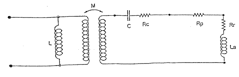
of the antenna The modelisation purpose is the definition of the electrical circuit
and the parameters of the antenna. It is made by the wire methods
of moments. The radiating element is represented by a radiating impedance (Rr, La)
with a loss resistance Rp The tuning capacitor is represented by a serial circuit (C, Rc), C being
the capacitor value and Rr its loss resistance. The 50 Establishment of the equivalent circuit parameters: -The radiating element (Rr, La) is calculated by an
electromagnetism software based upon the method of moments.
- The radiating element loss Rp is determined according to the antenna
material and section - The capacitor's losses Rc are determined through the manufacturer's
data - The matching
ratio K is a function of the primary to secondary radiating surface
ratio |
- The inductance L is a function of the spiral surface comprised between
the feed bar and the platform. Two types of antennas have been compared, type A and type B, differing
by the positions of their capacitors. II.3. Modelisation
of the antenna type A The capacitor is positioned in the secondary
of the transformer, at the end of the line (FIG 1).
Figure
1 The electrical equivalent sheme is given FIG 2
Figure
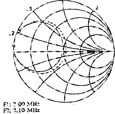
2 The results are computed by a specific C.A.D. radiofrequency device and
compared to the values measured on full scale antenna mock-up. As an example, FIG 3, FIG 4, FIG 5
show the
Figure 3 |
|
|
|
|
|
|
|
Page 36 |
|
 |
 |
 |
 |
Just for Fun:

Powered byIP2Location.com
Thanks for your time!
Last Updated:
February 9, 2018 21:28