

|
|
 |
 |
 |
|
|
Antentop is FREE e-magazine devoted to Antennas and Amateur Radio an
Special page devoted to
Half-Loop Antennas

Custom Search
|
ANTENTOP-
03- 2003, # 004 |
Half-Loop Antennas
|
|
|
|
|
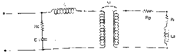
The equivalent circuit aided in the calculation of the voltages and the
currents developed over each electronic component. II. 4.
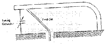
Modelisation of the antenna type B The tuning capacitor
is positioned in the primary of the autotransformer (FIG 8).
Figure 8 Its equivalent electrical scheme is given on FIG 9.
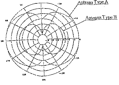
II.5. Compared performances type A and type B antennas Comparative simulations The comparative
simulated results were confirmed by the comparative measured bandwidths
Using 2 antennas having the same radiating surface, the compared
measured bandwidths were 5 to 10 times |
Figure 10 higher for the Type B than for the Type A antenna. In a tuned
circuit, bandwidths (B) are inversely proportional to the quality
factor (Q), and Q is proportional to the efficiency (h ); when
Q >> 1, h x B = Rr/2p La = constant If ha and hb are the
Type A and Type B antenna efficiencies , and Ba et Bb their bandwidths
respectively, the applying formulas are ha Ba = hb Bb, and ha
/ hb = Bb / Ba When the measured bandwidth ratios is Bb / Ba =
10 , the efficiency ratio becomes ha/hb is 10. Explanation
Observing that Type B antenna optimizes the tuning in the primary circuit,
and that the Q-factors of primary and secondary are quite different,
the energy transfer in the secondary is not maximized. On the
contrary, in the Type A antenna the tuning
brings a maximum Q-factor and the current is the highest in the
radiating resistor. Conclusion II.6 Improvement
of the design Increasing
the bandwith Such modifications can give an operational problem with no possible reset
in transmission (in FH mode principally). This shifting problem was resolved by widening the bandwidth by using
two radiating elements in parallel and electrically linked. The
simulation of this structure |
|
|
|
|
|
Page 38 |
 |
 |
 |
 |
Just for Fun:

Powered byIP2Location.com
Thanks for your time!
Last Updated:
February 9, 2018 21:30