

|
|
 |
 |
 |
|
|
Antentop is FREE e-magazine devoted to Antennas and Amateur Radio an
Special page devoted to
Half-Loop Antennas

Custom Search
|
ANTENTOP-
03- 2003, # 004 |
Half-Loop Antennas
|
|
|
|
||
|
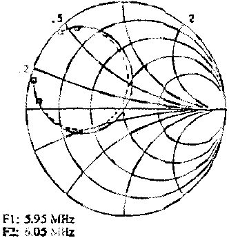
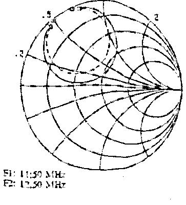
impedances
at various frequencies on the Smith charts, with computed values
(in full line) and measured values (in doted lines). These charts
underscore the performances of a resonating cavity like a
R, L, C parallel device, and confirm the impedance values computed
by the method of moments.
Figure 4
Figure 5 |
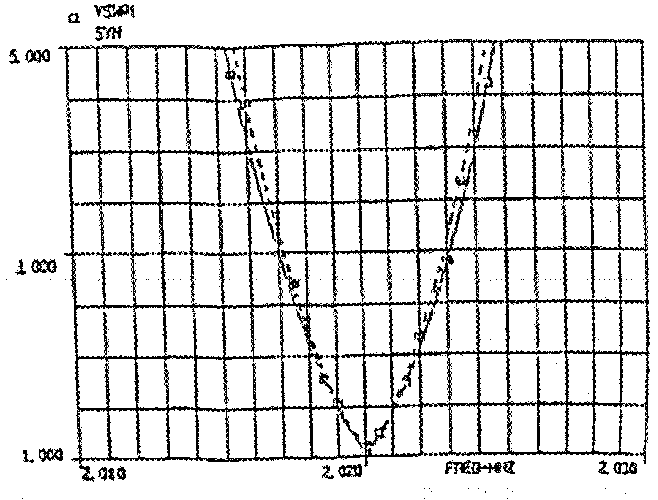
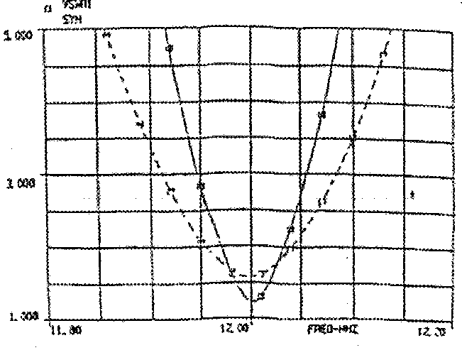
The calculated and measured values are compared at various frequencies
(FIG 6, FIG7)
The bandwidth is measured at VSWR ý 2.5:1
, when the real and the imaginary terms of the impedance
are equal.
Figure
6
Figure
7 The results have validated the antenna equivalent circuit. This sheme helped to optimize the dimensions of the radiating element,
considering the efficiency and bandwidth requirements. The approximative
values are, from 2 to 12 MHz: Rr = 0,5m Rp= 0.01 to 0.02 C= 3500 to 60 pF Rc= 0.05 to 2 |
|
|
|
|
|
|
|
Page 37 |
|
 |
 |
 |
 |
Just for Fun:

Powered byIP2Location.com
Thanks for your time!
Last Updated:
February 9, 2018 21:29