

|
|
 |
 |
 |
|
|
Antentop is FREE e-magazine devoted to Antennas and Amateur Radio an
Special page devoted to
Half-Loop Antennas

Custom Search
|
|
ANTENTOP-
03- 2003, # 004 |
Half-Loop Antennas
|
||
|
|
|
|||
|
|
Figure 11 modification concluded in a +10 to +15% extended bandwidths and
in +0.5dB to +1dB extra efficiencies all over the frequency range. II.7. Realisation
of a fast tune design The 2-12 MHz.antenna was developed for the required efficiency and a
minimum 3.5 kHz bandwidth independently of the variations in the
environment. With a 2.2m2 radiating surface the half-loop reactance is
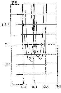
2mH at 2 MHz and 3.5mH at 12 MHz. The tuning principle consists in switching capacitors in parallel to
create a series of bandwidths with mutual covering at a VSWR <
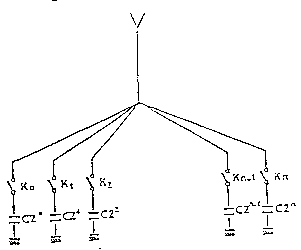
2.5:1.(FIG 12) Figure 12 |
Principle of the capacitor switching The capacitors which are necessary to tune the antenna reactance are
scaled from 3300pF to 60 pF at 2 MHz and 12 MHz respectfully,
with a 1,5 pF accuracy at the highest frequencies. A logarithmic series of n switchable capacitors in parallel defined by
Ci=2 Ci-1 with C1=1.5 pF give all discrete value multiple of 1,5pF:
C = S ki Ci from i = 1 to n , with ki= 0 ou 1 C1, which is the smallest used capacitor, defines the
accuracy of the C capacitor The highest individual capacitor value is in theory 3300/2=1650 pF in
order to get 3300pF by the addition of all capacitors, and n must
be higher than 10. The total number of capacitors is choosen equal to 12 to takto into consideration
the dispersion of the components whose values are guaranteed with
a ñ 5% precision, and to recover the possible missing frequency
bands. A special software was created to define and memorize the kiCi
arrangements which are necessary to get all discrete capacitor
values and recover the possible missing frequency bands. It memorizes
the calculated values and the measured values. A calibration at
the first installation or in operation in case of a major environment
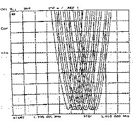
change can be done in less than 6 seconds. Measured results The prototype of the antenna achieved a VSWR 2.5:1.
Typical figures are
given FIG13. Figure 13 |
||
|
|
|
|
||
|
|
|
Page 39 |
||
 |
 |
 |
 |
Just for Fun:

Powered byIP2Location.com
Thanks for your time!
Last Updated:
February 9, 2018 21:31